Table of Contents
Advertisement
Quick Links
Advertisement
Table of Contents

Summary of Contents for Digalog Systems DigESwitch
- Page 1 DigESwitch Differential 4200-0352 V1.1...
-
Page 3: Table Of Contents
To Create A Driver Session ........................14 Software Installation: ..........................15 IVI Configuration ...............................15 To Create A Logical Name ........................17 Configuration and Setup ..........................19 DigESwitch Home Page .........................19 IP Configuration Page ..........................21 Changing the IP settings on the DigESwitch box ................25 DigESwitch Differential... - Page 4 Factory IP Configuration Default Settings ..................28 Block Diagram ............................32 Connector Pinout / Layout ........................33 Overview ................................34 Features: ..............................34 Front Panel ..............................37 Power LED ..............................37 Active LED ..............................37 Link LED ...............................38 Signal Connectors ............................38 Connector J1 ..............................39 Connector J2 ..............................40 Connector J3 ..............................41 DigESwitch Differential...
- Page 5 Connector J4 ..............................42 Connector J5 ..............................43 Rear Panel ..............................44 Specifications ..............................45 DigESwitch I/O Connectors (J1 – J5) ....................45 Relays................................45 System Operating Environment ......................46 DigESwitch Configurations ........................46 Power Requirements ..........................46 Fuses ................................47 Switching Speeds .............................47 High Frequency Specifications ......................47 Box Dimensions ............................48 IVI Compliance Category ..........................51...
- Page 6 Supported Calls - Error Information Functions ................54 Unsupported Calls - Interchangeability Checking Functions ..........55 Unsupported Calls - IviSwitchScanner Extension Group Functions ........55 Unsupported Calls - IviSwitchSoftwareTrigger Extension Group Functions ......55 Unsupported Calls - Utility Functions ....................55 IVI-C Switch Class-Compliant Specific Software ..................56 DigESwitch Differential...
- Page 7 Library (.dll) Software ..........................59 dlesw_Open ...............................60 dlesw_Close ...............................61 dlesw_GetFirmwareRev .........................62 dlesw_GetInstrumentModel ........................63 dlesw_Reset ...............................64 dlesw_ConnectChan..........................65 dlesw_DisconnectChan .........................66 dlesw_DisconnectAll ..........................67 dlesw_WriteChanImage ........................68 dlesw_ReadChanImage .........................69 dlesw_ReadBusImage ..........................71 dlesw_WriteBoardImage ........................72 dlesw_ReadBoardImage ........................73 DigESwitch Differential...
- Page 8 ........................80 dlesw_RelayUpdate ..........................81 Error Codes ..............................82 Library Call Code Examples ........................85 OVERVIEW OF TCP API.............................91 TCP Message Structure ..........................92 TCP Command Summary Table ......................93 TCP Command Listing ..........................94 0x01 Get Firmware Rev ..........................94 0x02 Board Reset ............................95 DigESwitch Differential...
- Page 9 0x05 Connect Channel ...........................96 0x06 Disconnect Channel ........................97 0x07 Disconnect All ..........................98 0x08 Number of Boards Present ......................99 0x09 Write Channel Image......................... 100 0x0A Read Channel Image......................... 101 0x0B Write Bus Image .......................... 102 0x0C Read Bus Image .......................... 103 0x0D Write Board Image ........................
- Page 10 0x20 Read Box Relay States ....................... 116 0x21 Set Relay Break Time ......................... 117 TCP Error Codes ............................. 118 Appendix A - Replacement Parts ......................119 Fuses ................................119 Relays................................. 119 DigESwitch I/O Connectors (J1 – J5) ....................119 Appendix B - Warranty ..........................121...
- Page 11 Installation Installation DigESwitch Differential...
-
Page 12: Hardware Installation
Install the (2) rack mount brackets (0000-8337) to each side of the DigESwitch box using the (6) black 8-32 (2825-0167) screws provided. Mount the DigESwitch box in the 19” rack using (4) clips (1400-1041) and (4) 10-32 screws (1400-3333) provided. -
Page 13: Software Installation
Software Installation There are two different software packages that can be used to program the DigESwitch. One software package installs only the DLL files necessary to program the DigESwitch from any programming language that uses the C function calling syntax. The other software package installs the necessary files for the DigESwitch to be programmed from an IVI-compatible programming environment. -
Page 14: To Create A Hardware Asset
Configuration Store Editor. Enter a name that specifies the hardware asset that is being added. For example: “DigESwitch” . Enter a description for the asset. This field is optional. An example would be “50 Channel Differential Switch” . -
Page 15: Software Installation
If the IVI drivers were installed, run the “ConfigStoreEditor Setup.exe” program on the Installation CD to install the Configuration Store Editor program. Follow the DigESwitch Hardware Configuration instructions. The software is now ready to use. IVI Configuration If installing the IVI drivers, use the Configuration Store Editor Program found at “C:\Program Files\Digalog\Configuration Store Editor and create the following... - Page 16 The “Sessions” entry is in the tree view on the left hand side of the Configuration Store Editor. Enter a name that specifies the driver session that is being added. For example: “DigESwitch” . Enter a description for the driver session. This field is optional. An example would be “50 Channel Differential Switch” .
-
Page 17: To Create A Logical Name
Right click on the “Logical Names” entry and select “Create New . . . “. This will create a new form where the Logical Name information can be entered. The “Logical Names” entry is in the tree view on the left hand side of the Configuration Store Editor. DigESwitch Differential... - Page 18 Installation Enter a name that specifies the logical name that is being added. For example: “DigESwitch” . If an existing logical name is being used, select that logical name and then select the Driver Session created for this card. Enter a description for the logical name. This field is optional. An example would be “50 Channel Differential Switch”...
-
Page 19: Configuration And Setup
Installation Configuration and Setup DigESwitch Home Page The DigESwitch Home page contains information about the DigESwitch box. The following information is displayed: Instrument Model The DigESwitch model number. Manufacturer Manufacturer name - Digalog Systems, Inc. Serial Number Serial number of the DigESwitch box. - Page 20 Installation Description Description of the DigESwitch box. This string can be configured by the user and may be changed on the IP Configuration page. Host Name Host name as resolved by the DNS server. This field will contain the assigned IP address if no host name is assigned to the DigESwitch box.
-
Page 21: Ip Configuration Page
Installation IP Configuration Page The IP Configuration page allows the user to change the IP Configuration of the DigESwitch box. The IP Configuration entries are: Hostname Hostname to use for all dynamic naming services (20 characters maximum). DigESwitch Differential... - Page 22 (20 characters maximum). Description User configurable string that can be used to describe the DigESwitch box (20 characters maximum). TCP/IP Mode Specifies the IP addressing mode to use. Auto mode uses the DHCP server to obtain the IP address. Manual mode attempts to connect to the network using the IP Address provided below.
- Page 23 Configuration settings. The name of any invalid entry will be marked in red. All entries must be valid before any of the IP Configuration settings are updated. Power to the DigESwitch box must be cycled before the new settings will take effect. DigESwitch Differential...
- Page 24 NOTE: All IP Addresses and SubNet Masks must be entered in the form of four numbers between 0 and 255 separated by periods. For example, 192.168.1.210 or 255.255.255.0. NOTE: Power to the DigESwitch box must be cycled before the new settings will take effect. DigESwitch Differential...
-
Page 25: Changing The Ip Settings On The Digeswitch Box
Installation Changing the IP settings on the DigESwitch box The DigESwitch box is configured in the factory to use a static IP Address of 197.2.2.2. The Subnet Mask is set to 255.255.255.0. The following outlines the steps required to reconfigure the IP Setting of the DigESwitch box: Connect the DigESwitch box to a PC either directly using a crossover Ethernet cable or through an Ethernet switch using a standard Ethernet cable. - Page 26 Network Connections window. Open an Internet Explorer window and type http://197.2.2.2 in the address box. The DigESwitch Home Page should be displayed. Click on the LAN Configuration link. Setup the IP Configuration as required. Press the Submit button when complete.
- Page 27 Installation Return the PC to its original IP Configuration. Cycle the power on the DigESwitch box to use the new IP Settings. NOTE: Pressing the LAN Reset button on the back of the DigESwitch box will restore the factory default settings.
-
Page 28: Customer Support Page
Installation Customer Support Page The Customer Support page lists the customer support contact information. Factory IP Configuration Default Settings The factory default IP Configuration settings are: DigESwitch Differential... - Page 29 Default Gateway: Blank DNS Server Addressing: Auto Preferred DNS Server: Blank Alternate DNS Server: Blank Dynamic DNS: Disabled The factory default settings can be restored by pressing the LAN Reset switch located on the back of the DigESwitch box. DigESwitch Differential...
- Page 30 Installation DigESwitch Differential...
- Page 31 Overview Overview DigESwitch Differential...
-
Page 32: Block Diagram
Overview Block Diagram A00 + A00 - B00 + B00 - Ch00 COM00 + COM00 - Relay Control Relay Control Lines A49+ A49 - 10/100 B49 + BaseT B49 - Ethernet Ch49 Block Diagram COM49 + COM49 - DigESwitch Differential... -
Page 33: Connector Pinout / Layout
Ch00 - Ch09 07 B- 07 B+ 08 A- 08 A+ 08 COM- 08 COM+ Connector Layout 08 B- 08 B+ 09 A- 09 A+ 09 COM- 09 COM+ 09 B- 09 B+ Typical Connector Connector Pinout / Layout Pinout DigESwitch Differential... -
Page 34: Overview
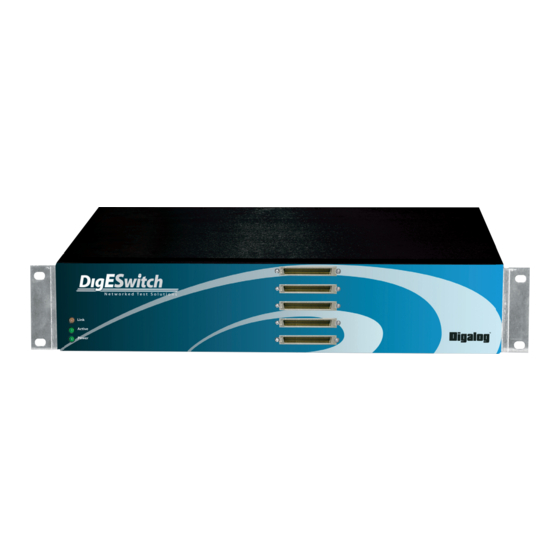
Industry-Standard IVI Driver • Support for National Instruments® Switch Executive™ The “DigESwitch Differential” is a versatile and low-cost 10/100BaseT Ethernet- controlled relay switching solution housed in a compact 2U 19” rack-mount chassis. Its full-capacity configuration features 50 independent two-input differential channels with A, B, AB and Disconnect modes. Each channel can switch up to 0.5A or carry up to 1.0A with 150VDC/100VAC off-state isolation. - Page 35 Overview The DigESwitch Differential can be utilized as a standalone Ethernet appliance, or as an integrated component of existing or planned test systems where it gives the user a simple yet versatile capability for routing and control of resources. Relay programming options include both a Direct I/O driver and the industry-standard IVI driver.
- Page 36 Hardware Hardware DigESwitch Differential...
-
Page 37: Front Panel
Hardware Front Panel The front panel of the DigESwitch chassis houses the five (maximum configuration) board connectors and three status LEDs. The LEDs indicate the following status: Power LED The green Power LED located on the front panel indicates the power status. -
Page 38: Link Led
Hardware the DigESwitch Ethernet port. Link LED The bi-color Link LED located on the front panel indicates the DigESwitch Ethernet link status. This LED is lit green if the link is okay or red if the link failed. Signal Connectors The pin designations for each connector are shown below. -
Page 39: Connector J1
32 - N/C 49 - CH4 B- 66 - N/C 16 - CH5 A+ 33 - N/C 50 - CH5 A- 67 - N/C 17 - CH5 COM+ 34 - N/C 51 - CH5 COM- 68 - N/C DigESwitch Differential... -
Page 40: Connector J2
32 - N/C 49 - CH14 B- 66 - N/C 16 - CH15 A+ 33 - N/C 50 - CH15 A- 67 - N/C 17 - CH15 COM+ 34 - N/C 51 - CH15 COM- 68 - N/C DigESwitch Differential... -
Page 41: Connector J3
32 - N/C 49 - CH24 B- 66 - N/C 16 - CH25 A+ 33 - N/C 50 - CH25 A- 67 - N/C 17 - CH25 COM+ 34 - N/C 51 - CH25 COM- 68 - N/C DigESwitch Differential... -
Page 42: Connector J4
32 - N/C 49 - CH34 B- 66 - N/C 16 - CH35 A+ 33 - N/C 50 - CH35 A- 67 - N/C 17 - CH35 COM+ 34 - N/C 51 - CH35 COM- 68 - N/C DigESwitch Differential... -
Page 43: Connector J5
32 - N/C 49 - CH44 B- 66 - N/C 16 - CH45 A+ 33 - N/C 50 - CH45 A- 67 - N/C 17 - CH45 COM+ 34 - N/C 51 - CH45 COM- 68 - N/C DigESwitch Differential... -
Page 44: Rear Panel
Hardware Rear Panel The rear panel of the DigESwitch chassis houses the Reset Switch and the Power Recepticle/On/Off Switch as shown below. The On/Off Switch assembly fuse(s) are rated at 3A/250VAC, 3AG SloBlo (North America) or (2) 3.15A x 250VAC SloBlo (Europe). Complete specifications are listed in the next section. -
Page 45: Specifications
Hardware Specifications DigESwitch I/O Connectors (J1 – J5) AMP 2-174225-5 Relays Type SPST (Form A) Static Contact Resistance 400mohms (Maximum Initial) Max Switching Voltage 150VDC, 100VAC Peak Max Switching Current 0.5ADC, 0.5AAC Peak Max Switching Power Max Carry Current 1A, 1A-AC Peak... -
Page 46: System Operating Environment
Hardware System Operating Environment Operating Temperature 0 - 35°C, 32 - 95°F Humidity 20% to 80% Relative Humidity Altitude less than 2000m DigESwitch Configurations 0004-5201A 10 Two-Input Differential Channels 0004-5201B 20 Two-Input Differential Channels 0004-5201C 30 Two-Input Differential Channels 0004-5201D... -
Page 47: Fuses
Europe (2) 3.15A/250VAC, .5 x 20mm, Slo-Blo, LittleFuse 2183.15XP Switching Speeds Dlesw_ConnectChan 3.2ms Dlesw_DisconnectChan 4.0ms Dlesw_WriteBoxImage 32.1ms High Frequency Specifications Gain at 15MHz -1dB Gain at 45MHz -3dB Adjacent Channel Crosstalk < -50dB at 5.0MHz. <-20dB at 45MHz DigESwitch Differential... -
Page 48: Box Dimensions
Hardware Box Dimensions 19” Rackmount 2U (3.44”) high x 18” deep Weight - Less than 35Lbs. - Maximum Configuration DigESwitch Differential... - Page 49 Hardware DigESwitch Differential...
- Page 50 IVI Switch Class IVI Switch Class DigESwitch Differential...
-
Page 51: Ivi Compliance Category
Not Supported Optional Features: Range Check False Query Instrument Status False State Caching True Simulate False Coercion Recording False Interchangeability Checking False Driver Identification: Driver Revision: Driver Vendor: Digalog Systems Inc. Prefix: DLESW Description: 50 Channel Differential Switch DigESwitch Differential... -
Page 52: Software Information
IVI Switch Class Hardware Information: Instrument Manufacturer: Digalog Systems Inc. Supported Instrument Models: 5201A, B, C, D, & E Supported Bus Interfaces: TCP/IP Software Information: Support Software Required: National Instruments IVI Engine ver 2.1 or later Source Code Availability: Source code not available. -
Page 53: Supported Calls - Iviswitchbase Capability Group Functions
ViStatus IviSwtch_WaitForDebounce (ViSession vi, ViInt32 maxTime); Supported Calls - Utility Functions ViStatus IviSwtch_ResetWithDefaults (ViSession vi); ViStatus IviSwtch_Disable (ViSession vi); Supported Calls - Set and Get Check Attribute Functions ViStatus IviSwtch_GetAttributeViInt32 (ViSession vi, ViConstString channelName, ViAttr attributeId, ViInt32 *value); DigESwitch Differential... -
Page 54: Supported Calls - Lock And Unlock Functions
Supported Calls - Lock and Unlock Functions ViStatus IviSwtch_LockSession (ViSession vi, ViBoolean *callerHasLock); ViStatus IviSwtch_UnlockSession (ViSession vi, ViBoolean *callerHasLock); Supported Calls - Error Information Functions ViStatus IviSwtch_GetError (ViSession vi, ViStatus *errorCode, ViInt32 bufferSize, ViChar description[]); ViStatus IviSwtch_ClearError (ViSession vi); DigESwitch Differential... -
Page 55: Unsupported Calls - Interchangeability Checking Functions
ViStatus IviSwtch_SendSoftwareTrigger (ViSession vi); Unsupported Calls - Utility Functions ViStatus IviSwtch_InvalidateAllAttributes (ViSession vi); ViStatus IviSwtch_self_test (ViSession vi, ViInt16 *selfTestResult, ViChar selfTestMessage[]); ViStatus IviSwtch_error_query (ViSession vi, ViInt32 *errorCode, ViChar errorMessage[]); ViStatus IviSwtch_CheckAttributeViInt32 (ViSession vi, ViConstString channelName, ViAttr attributeId, ViInt32 value); DigESwitch Differential... -
Page 56: Ivi-C Switch Class-Compliant Specific Software
C:\Program Files\IVI\Include Contains the header file to use with the application. C:\Program Files\IVI\Bin Contains the DLL for the IVI Switch software. C:\Program Files\IVI\Drivers\dlesw Contains the LabWindows/CVI function panels and help for the DigESwitch IVI class- compliant specific calls. DigESwitch Differential... - Page 57 IVI Switch Class DigESwitch Differential...
- Page 58 Library Calls Library Calls DigESwitch Differential...
-
Page 59: Library (.Dll) Software
C:\digalog\cvi\lib\msc Contains the library file to include with the application. C:\digalog\cvi\include Contains the header file to use with the application. C:\digalog\cvi\functionpanels Contains the LabWindows/CVI function panels for the Library calls. C:\Windows\System32 Contains the DLL for the Library calls. DigESwitch Differential... -
Page 60: Dlesw_Open
Returns the handle to the DigESwitch box. Note that a zero can be a valid handle. LocalIP This is the IP address or host name of the DigESwitch box. It can be either an alphabetical string such as xyz.abc.com, or a numerical string such as 197.2.2.2. -
Page 61: Dlesw_Close
CVI Declaration: int32 dlesw_Close (u_int32 SessionHandle); Where: SessionHandle Handle used to access the DigESwitch box. This handle is returned from dlesw_Open ( ). Return This function returns a zero upon success, or a non-zero number upon error. DigESwitch Differential... -
Page 62: Dlesw_Getfirmwarerev
Library Calls dlesw_GetFirmwareRev This function gets the firmware revision string from the DigESwitch box. The character array which will hold the firmware revision string must be at least 20 characters (bytes) in size. Header File: dlesw_foundation.h CVI Declaration: int32 dlesw_GetFirmwareRev (u_int32 SessionHandle, u_int16 *RevStrSize, char RevStr);... -
Page 63: Dlesw_Getinstrumentmodel
Library Calls dlesw_GetInstrumentModel This function gets the model string from the DigESwitch box. The number of boards in the box determines the model number; i.e. models 0004-5201A, B, C, D and E have one, two, three, four or five boards respectively. -
Page 64: Dlesw_Reset
Header File: dlesw_foundation.h CVI Declaration: int32 dlesw_Reset (u_int32 SessionHandle); Where: SessionHandle Handle used to access the DigESwitch box. This handle is returned from dlesw_Open (). Return This function returns a zero upon success, or a non-zero number upon error. DigESwitch Differential... -
Page 65: Dlesw_Connectchan
Chan The channel on which you with to connect a port. Valid ranges are 0 - 9 (one-board DigESwitch), 0 - 19 (two boards), 0 - 29 (three boards), 0 - 39 (four boards) and 0 - 49 (five boards). -
Page 66: Dlesw_Disconnectchan
Chan The channel on which you with to disconnect a port. Valid ranges are 0 - 9 (one-board DigESwitch), 0 - 19 (two boards), 0 - 29 (three boards), 0 - 39 (four boards) and 0 - 49 (five boards). -
Page 67: Dlesw_Disconnectall
CVI Declaration: int32 dlesw_DisconnectAll (u_int32 SessionHandle, int16 bdNum); Where: SessionHandle Handle used to access the DigESwitch box. This handle is returned from dlesw_Open ( ). BdNum The board on which you wish to open all relays and disconnect all ports. Valid range 0 - 4. -
Page 68: Dlesw_Writechanimage
Library Calls dlesw_WriteChanImage NOTE: This call is valid only with the matrix models of DigESwitch. It will return a “Not Supported” error if used with a differential unit. For further information refer to the user manual for the matrix models. -
Page 69: Dlesw_Readchanimage
Library Calls dlesw_ReadChanImage NOTE: This call is valid only with the matrix models of DigESwitch. It will return a “Not Supported” error if used with a differential unit. For further information refer to the user manual for the matrix models. - Page 70 Library Calls dlesw_WriteBusImage NOTE: This call is valid only with the matrix models of DigESwitch. It will return a “Not Supported” error if used with a differential unit. For further information refer to the user manual for the matrix models.
-
Page 71: Dlesw_Readbusimage
Library Calls dlesw_ReadBusImage NOTE: This call is valid only with the matrix models of DigESwitch. It will return a “Not Supported” error if used with a differential unit. For further information refer to the user manual for the matrix models. -
Page 72: Dlesw_Writeboardimage
Library Calls dlesw_WriteBoardImage NOTE: This call is valid only with the matrix models of DigESwitch. It will return a “Not Supported” error if used with a differential unit. For further information refer to the user manual for the matrix models. -
Page 73: Dlesw_Readboardimage
BdImageArrSize, u_char *BdImageArr); Where: SessionHandle Handle used to access the DigESwitch box. This handle is returned from dlesw_Open ( ). BdNum The board whose image you want to retrieve. Valid range = 0 - 4, with the maximum being being determined by the number of boards in the box. Board #0 is the bottom board and corresponds to channels 0 - 9, while the top board is #4 and carries channels 40 - 49. - Page 74 Note: This function reads the board image which may differ from the actual state of the board’s relays in the case where a new image has been written but the dlesw_RelayUpdate( ) function has not been called yet to actually apply the new image to the board. DigESwitch Differential...
-
Page 75: Dlesw_Writeboximage
This function writes an image of all relays in the DigESwitch box. The channel image consists of one char (byte) for each channel in a box, i.e. 50 chars (10 chars per board x 5 boards) for a fully configured DigESwitch. - Page 76 Library Calls dlesw_ReadBoxImage This function reads the complete on-board channel image for all the boards in a DigESwitch box. The channel image consists of one char (byte) for each of the channels in a box, i.e. 50 chars (10 chars per board x 5 boards) for a fully configured DigESwitch.
-
Page 77: Dlesw_Readchanrelaystates
The channel number whose state is to be read. Valid range = 0 to 49 for a fully configured DigESwitch, 0 to 9 for a one-board box, 0 to 19 for two boards, 0-29 for three boards and 0-39 for four boards. -
Page 78: Dlesw_Readbusrelaystates
Library Calls dlesw_ReadBusRelayStates NOTE: This call is valid only with the matrix models of DigESwitch. It will return a “Not Supported” error if used with a differential unit. For further information refer to the user manual for the matrix models. -
Page 79: Dlesw_Readboardrelaystates
CVI Declaration: int32 dlesw_ReadBoardRelayStates (u_int32 SessionHandle, u_int16 BdNum, u_int16 BdRelayArrSize, u_char *BdRelayArr); Where: SessionHandle Handle used to access the DigESwitch box. This handle is returned from dlesw_Open ( ). BdNum The board in the DigESwitch box to read Valid values = 0 to 4. -
Page 80: Dlesw_Readboxrelaystates
This function reads the current state of all channel relays on all the boards. The channel relay state consists of one char (byte) for each of the channels in a box, up to 50 chars for a fully configured DigESwitch. -
Page 81: Dlesw_Relayupdate
0. Any other value will return a “Parameter not valid” error. Mode Relay Switching Mode. This version of DigESwitch supports only the “Break Before Make” mode, so the only valid value for this parameter is 2. Any other value will return a “Parameter not valid” error. Return This function returns a zero upon success, or a non-zero number upon error. -
Page 82: Error Codes
Write failed. ERR_TCP_INVALID_PARAM Invalid Parameter. ERR_TCP_OUT_OF_MEMORY Out of memory. ERR_TCP_TIMEOUT Time Out Error. ERR_TCP_NO_CONNECT_MADE Could not established a connection between the host PC and the DigESwitch. ERR_TCP_GENERAL_IO General IO Error. ERR_TCP_CONNECT_CLOSED The connection to the DigESwitch is closed. DigESwitch Differential... - Page 83 Unable to load Winsock DLL. ERR_TCP_WINSOCK_VERSION Incorrect Winsock DLL Version. ERR_TCP_NETWORK_PROBLEM Network subsystem not ready. ERR_TCP_CONNECT_STILL_OPEN Connections to the DigESwitch are still open. ERR_TCP_DISCONNECT_PENDING Disconnect pending. ERR_TCP_NO_INFO Info not available, generic driver error. ERR_TCP_HOST_ADDR_NOT_FOUND Host Address not Found. -100 ERR_TCP_RET_BUF_TOO_SMALL The return buffer string is too small.
- Page 84 UNSUPPORTED model of DigESwitch. ERR_ESWITCH_PARAM2_VALUE_ The passed value of the 2nd parameter is not UNSUPPORTED supported by this model of DigESwitch. ERR_ESWITCH_PARAM3_VALUE_ The passed value of the 3rd parameter is not UNSUPPORTED supported by this model of DigESwitch. DigESwitch Differential...
-
Page 85: Library Call Code Examples
Library Calls Library Call Code Examples Example 1: This example shows how to open a session to the DigESwitch box, manipulate the channel connections, and then close the session. u_int32 DleswHandle; int32 DleswErr; //Obtain a handle to the DigESwitch box. - Page 86 //This will break the connection between channel #0 B+ and B- inputs //and the channel #0 COM+ and COM- outputs. if ((DleswErr = dlesw_DisconnectChan (DleswHandle, 0, 1)) != 0) //Error-handling code //Free the handle to the DigESwitch box. if ((DleswErr = dlesw_Close(DleswHandle)) != 0) //Error-handling code DigESwitch Differential...
- Page 87 Library Calls Example 2: This example shows how to open a session to the DigESwitch box, manipulate the channel connections using the box image calls, and then close the session. NOTE: No error handling is performed in order to make the example more readable. See Example 1 for error handling techniques.
- Page 88 //board before, and remain 0 (all relays open) for the other four boards. DleswErr = dlesw_ReadBoxImage (DleswHandle, 50, *BoxReadImageArray); //Reset the box so that all channel relays are open. DleswErr = dlesw_Reset (DleswHandle); //Free the handle to the DigESwitch box. DleswErr = dlesw_Close (DleswHandle); DigESwitch Differential...
- Page 89 Library Calls DigESwitch Differential...
- Page 90 TCP API TCP Application Programming Interface (API) DigESwitch Differential...
-
Page 91: Overview Of Tcp Api
TCP. The actual number of bytes involved for a particular command will in some cases depend on the exact DigESwitch model being used; i.e. the number of boards installed. These differences are noted with the commands affected. -
Page 92: Tcp Message Structure
The microcontroller has a buffer to store incoming messages. Host Message Structure uC Message Structure Byte Description Byte Description Command Status D0 - Data Byte 0 Data Byte 0 D1 - Data Byte 1 Data Byte n Dn - Data Byte n Data Byte n DigESwitch Differential... -
Page 93: Tcp Command Summary Table
Write Board Image 0x1E Write Box Image 0x0E Read Board Image 0x1F Read Box Image 0x0F Read Channel Relay State 0x20 Read Box Relay State 0x10 Read Bus Relay State 0x21 Set Relay Break Time 0x11 Read Board Relay State DigESwitch Differential... -
Page 94: Tcp Command Listing
“w” denotes a word (2 bytes). 0x01 Get Firmware Rev This function gets the firmware revision string from the DigESwitch box. On successful execution the function returns a byte array with a minimum length of 20. Host TCP Command Packet... -
Page 95: 0X02 Board Reset
TCP API 0x02 Board Reset This function opens all the connections in a DigESwitch box and clears all board image locations. Host TCP Command Packet Byte# Value/Type Description 0x02 Command Byte DigESwitch Response Packet Byte# Value/Type Description Status Byte / non-zero value = error code... - Page 96 Host TCP Command Packet Byte# Value/Type Description 0x05 Command Byte Channel (MSB-LSB) (0 - 49) Port (A = 0x0000, B = 0x0001, A&B = 0xFFFF) DigESwitch Response Packet Byte# Value/Type Description 0x00 Status Byte / non-zero value = error code DigESwitch Differential...
- Page 97 Host TCP Command Packet Byte# Value/Type Description 0x06 Command Byte Channel (MSB-LSB) (0 - 49) Port (A = 0x0000, B = 0x0001, A&B = 0xFFFF) DigESwitch Response Packet Byte# Value/Type Description 0x00 Status Byte / non-zero value = error code DigESwitch Differential...
- Page 98 Command Byte Board (MSB-LSB) Range: -1 (0xFF) = Disconnect all boards (0 -4) = Disconnect specified board only (See board specifications for valid channel range) DigESwitch Response Packet Byte# Value/Type Description 0x00 Status Byte / non-zero value = error code...
- Page 99 TCP API 0x08 Number of Boards Present This function retrieves the number of boards installed in the DigESwitch box. Host TCP Command Packet Byte# Value/Type Description 0x08 Command Byte DigESwitch Response Packet Byte# Value/Type Description 0x00 Status Byte / non-zero value = error code...
- Page 100 TCP API 0x09 Write Channel Image This command is not supported by the DigESwitch Differential model and will return an error if used. DigESwitch Response Packet Byte# Value/Type Description 0x14 “Not Supported” error DigESwitch Differential...
- Page 101 TCP API 0x0A Read Channel Image This command is not supported by the DigESwitch Differential model and will return an error if used. DigESwitch Response Packet Byte# Value/Type Description 0x14 “Not Supported” error DigESwitch Differential...
- Page 102 TCP API 0x0B Write Bus Image This command is not supported by the DigESwitch Differential model and will return an error if used. DigESwitch Response Packet Byte# Value/Type Description 0x14 “Not Supported” error DigESwitch Differential...
- Page 103 TCP API 0x0C Read Bus Image This command is not supported by the DigESwitch Differential model and will return an error if used. DigESwitch Response Packet Byte# Value/Type Description 0x14 “Not Supported” error DigESwitch Differential...
- Page 104 TCP API 0x0D Write Board Image This command is not supported by the DigESwitch Differential model and will return an error if used. DigESwitch Response Packet Byte# Value/Type Description 0x14 “Not Supported” error DigESwitch Differential...
- Page 105 TCP API (This page intentionally left blank) DigESwitch Differential...
- Page 106 TCP API 0x0E Read Board Image This command is not supported by the DigESwitch Differential model and will return an error if used. DigESwitch Response Packet Byte# Value/Type Description 0x14 “Not Supported” error DigESwitch Differential...
- Page 107 TCP API (This page intentionally left blank) DigESwitch Differential...
- Page 108 Host TCP Command Packet Byte# Value/Type Description 0x0F Command Byte Channel (MSB-LSB) (Valid values 0 - 49) DigESwitch Response Packet Byte# Value/Type Description 0x00 Status Byte / non-zero value = error code Channel Status value read. An 8-bit value representing the channel connections: 0X00 = A &...
- Page 109 TCP API 0x10 Read Bus Relay State This command is not supported by the DigESwitch Differential model and will return an error if used. DigESwitch Response Packet Byte# Value/Type Description 0x14 “Not Supported” error DigESwitch Differential...
- Page 110 TCP API 0x11 Read Board Relay State This command is not supported by the DigESwitch Differential model and will return an error if used. DigESwitch Response Packet Byte# Value/Type Description 0x14 “Not Supported” error DigESwitch Differential...
- Page 111 (see board specifications for the channel range) Mode: 1 = Update relay states using the “normal” switching mode. 2 = Update relay states using “break-before-make” mode (2ms delay) DigESwitch Response Packet Byte# Value/Type Description 0x00 Status Byte / non-zero value = error code...
- Page 112 TCP API 0x1B Get Instrument Model This function retrieves the model number of the DigESwitch box. The number corresponds to the number of boards installed in the box. The character array passed, which will contain the returned model number string, must be at least 20 characters in length.
- Page 113 0x1E Write Box Image This function writes the complete on-board image for all boards in the DigESwitch box. The image consists of one byte for every channel in the box, but only the two low order bits are used. The actual relay states may be simultaneously updated if desired, or this function can write only the image, with the intention that the actual relay states will be updated later using the Relay Update function.
- Page 114 1: (2n+12) -> (2n+21) 2: (2n+22) -> (2n+31) ----------------------------------------------------------------------------- 3: (2n+32) -> (2n+41) PortB PortA 4: (2n+42) -> (2n+51) ----------------------------------------------------------------------------- PortX bit value 0 = channel is disconnected from channel COM output. Bit value 1 = channel is connected to output. DigESwitch Differential...
- Page 115 This function reads the complete on-board image for all boards in the DigESwitch box. The image consists of one byte for every channel in the box, up to 50 bytes for a fully configured DigESwitch Differential. The retrieved image may not correspond to the actual physical state of the box relays if a new image has previously been written but the Relay Update command has not yet been used to to change the relay states.
- Page 116 0x20 Read Box Relay States This function reads the actual current state of all channel relays on all boards in the DigESwitch box. The relay state consists of one byte for each of the channels in the box, up to 50 bytes for a fully-configured DigESwitch Differential.
- Page 117 2ms, so you only need to use Set Relay Break Time if you want a longer break. Host TCP Command Packet Byte# Value/Type Description 0x21 Command Byte Relay break time in milliseconds (valid values: 2 -> 500) DigESwitch Response Packet Byte# Value/Type Description 0x00 Status Byte / non-zero value = error code DigESwitch Differential...
- Page 118 TCP API TCP Error Codes Each command’s return value in Byte #0 of the DigESwitch response packet represents a code which indicates either success, or an error or warning condition. The calling software must examine the returned status code to determine if an error occurred. General meanings of the various status codes include:...
- Page 119 Appendix A - Replacement Parts Fuses North America 3A/250V, 3AG Slo-Blo, LittleFuse 313003P Europe (2) 3.15A/250VAC, .5 x 20mm, Slo-Blo, LittleFuse 2183.15XP Relays Type SPST (Form A) Replacement Relays Coto – 9001-05-01 DigESwitch I/O Connectors (J1 – J5) AMP 2-174225-5 Mating Connectors DigESwitch Differential...
- Page 120 Appendix A - Replacement Parts DigESwitch Differential...
- Page 121 Systems. Any equipment returned after authorization has been given must be shipped prepaid and insured at buyer’s expense. All circuit boards to be returned to Digalog Systems must be shipped in static shielding bags and packed in anti-static packaging material.
- Page 122 Appendix B - Warranty Digalog Systems will pay the return freight, within the continental United States, where a warranty adjustment is made. Digalog Systems is not liable for consequential damages. If Digalog Systems determines that no failure exists or that damage was created by negligence or misuse, the user will be invoiced for all repair and troubleshooting costs.
- Page 123 Appendix B - Warranty THIS WARRANTY IS IN LIEU OF ALL OTHER OBLIGATIONS OR LIABILITIES ON THE PART OF DIGALOG SYSTEMS. DIGALOG SYSTEMS DOES NOT AUTHORIZE ANY OTHER PARTY TO ASSUME ANY OTHER REPRESENTATION OR WARRANTY ON DIGALOG SYSTEM’S BEHALF, NOR DOES IT AUTHORIZE ANY OTHER PARTY TO ASSUME LIABILITY IN CONNECTION WITH THE SALE OF DIGALOG SYSTEM’S...
- Page 124 Appendix B - Warranty DigESwitch Differential...
Need help?
Do you have a question about the DigESwitch and is the answer not in the manual?
Questions and answers