Table of Contents
Advertisement
Quick Links
Advertisement
Table of Contents

Summary of Contents for fann 300 Series
- Page 1 Series 300 LPLT Filter Press Instruction Manual Manual No. 207128, Revision G...
- Page 2 Printed in USA. The information contained in this document includes concepts, methods, and apparatus which may be covered by U.S. Patents. Fann Instrument Company reserves the right to make improvements in design, construction, and appearance of our products without prior notice.
-
Page 3: Table Of Contents
LPLT Filter Press Instruction Manual Table of Contents Introduction ......................6 1.1 Document Conventions ..................7 Safety ........................8 2.1 Safe Pressurization ..................8 Features and Specifications ................... 10 Pressure Sources ....................11 4.1 Carbon Dioxide Pressure Source ..............11 4.2 Nitrogen Cylinder Pressure Source .............. - Page 4 LPLT Filter Press Instruction Manual List of Figures Figure 3-1 Basic Filter Press Assembly ................ 10 Figure 4-1 CO Cartridge Holder Assembly..............12 Figure 6-1 Cell Assembly ....................19 Figure 8-1 CO Pressure Assembly Drawing, P/N 208647 ..........23 Figure 8-2 Nitrogen Regulator Assembly Drawing, P/N 208652 ........24 Figure 10-1 Series 300 LPLT Filter Press, Basic Assembly ..........
- Page 5 LPLT Filter Press Instruction Manual List of Tables Table 3-1 Basic Filter Press Assembly Specifications ........... 10 Table 9-1 Optional Equipment ..................26 Table 10-1 Filter Press, Basic Assembly, P/N 207127 ..........27 Table 10-2 Filter Press Assembly w/Air Hose, P/N 207173 ........... 28 Table 10-3 Filter Press Assembly w/Regulator, P/N 207174 .........
-
Page 6: Introduction
LPLT Filter Press Instruction Manual Introduction Fann’s Series 300 LPLT Filter Press is used for measuring filtration and wall- building properties of drilling fluids and cement slurries. The filtration rate is the fluid loss measured in milliliters at ambient temperature and 100 psi (690 kPa) through a special filter paper for 30 minutes. -
Page 7: Document Conventions
LPLT Filter Press Instruction Manual Document Conventions The following icons are used in this manual. NOTE. Notes emphasize additional information that may be useful to the reader. CAUTION. Describes a situation or practice that requires operator awareness or action in order to avoid undesirable consequences. MANDATORY ACTION. -
Page 8: Safety
LPLT Filter Press Instruction Manual Safety Safe operation of filter presses requires that the laboratory technician or drilling fluids engineer be familiar with the proper operation and potential hazards associated with this equipment. For instance, if the filter cell or pressurization equipment has a leak, then sample or pressurizing fluid could be released and cause serious injury. - Page 9 LPLT Filter Press Instruction Manual 2.1.2 Pressure Regulators Maintain pressure regulators in good condition. Never use oil on pressure regulators. Pressurization systems that leak should be repaired or replaced. Gauges, fittings and hoses should be kept in good condition and leaks should be corrected.
-
Page 10: Features And Specifications
LPLT Filter Press Instruction Manual Features and Specifications This filter press is used in a static filtration test to measure fluid loss and filter cake characteristics of drilling fluids. The basic filter press assembly consists of the filter press unit and accessories, listed in Section 10. -
Page 11: Pressure Sources
Keep the CO cartridges away from extreme heat. Fann Instrument Company offers an extended CO cartridge barrel kit (P/N 101758212). This kit consists of an extended barrel and a polyurethane ball. This extended barrel can accept CO cartridges that are longer than the standard cartridge, as well as standard cartridges. -
Page 12: Figure 4-1 Co 2 Cartridge Holder Assembly
LPLT Filter Press Instruction Manual Figure 4-1 CO Cartridge Holder Assembly 207128 Revision G, September 2012... -
Page 13: Nitrogen Cylinder Pressure Source
LPLT Filter Press Instruction Manual Nitrogen Cylinder Pressure Source Follow this procedure to pressurize the filter press with a nitrogen cylinder. Refer to the assembly in Figure 10-4 which shows a filter press with a nitrogen regulator. 1. With the regulator adjusting screw backed out to the closed position (maximum outward), slowly open the pressure valve on the cylinder. -
Page 14: Dead-Weight Hydraulic Pressure Source
LPLT Filter Press Instruction Manual Dead-Weight Hydraulic Pressure Source The Dead-Weight Hydraulic Filter Press is a Series 300 Filter Press equipped with a dead-weight hydraulic assembly. See Figure 10-6. Follow this procedure to pressurize the filter press with the dead-weight hydraulic pressure source. -
Page 15: External Pressure Source
LPLT Filter Press Instruction Manual External Pressure Source A compressed air source that supplies more than 100 psi (690 kPa) is suitable to pressurize this filter press. A regulator is required. You can attach any regulator that meets the specific requirements for compressed air, nitrogen or carbon dioxide. -
Page 16: Installation
LPLT Filter Press Instruction Manual Installation The filter press can generally be arranged to suit the available space and the desires of the lab personnel, consistent with any established work processes. Consideration should be given to the location where samples are prepared and the cell is cleaned following test completion. -
Page 17: Standard Filter Press Test Procedures
LPLT Filter Press Instruction Manual Standard Filter Press Test Procedures Follow this procedure to operate the filter press with a compressed gas or dead- weight hydraulic pressure source. 1. Assemble the clean, dry parts of the filter cell (Figure 6-1) in the following order: a) base cap b) rubber gasket... - Page 18 LPLT Filter Press Instruction Manual 9. Measure the volume of filtrate collected in the graduated cylinder. Record the volume in milliliters as the API 30 minute filtrate loss of the drilling fluid. 10. Loosen the T-screw, remove the cell top, and then remove the cell from the frame.
-
Page 19: Figure 6-1 Cell Assembly
LPLT Filter Press Instruction Manual Top Cap (382949) Stop Mud Felt (208626) Rubber Gasket (208255) Cell Body (382948) Rubber Gasket Filter Paper (208255) (206051) Screen (208310) Rubber Gasket (208255) Base Cap with Filtrate Tube (382950) Figure 6-1 Cell Assembly 207128 Revision G, September 2012... -
Page 20: Test Analysis
LPLT Filter Press Instruction Manual Test Analysis References API Recommended Practice for Field Testing Water Based Drilling Fluids, API RP 13B-1 API Recommended Practice for Field Testing Oil Based Drilling Fluids, API RP 13B-2 Results The fundamental filtration measurements include the filtrate volume and filter cake thickness. -
Page 21: Troubleshooting And Maintenance
Troubleshooting and regular maintenance procedures are described in this section. If more extensive maintenance or service of the instrument is required, please contact Fann Instrument Company. Cleaning After each use, disassemble and clean the filter press cell. Wash and thoroughly rinse all drilling fluid from the cell. - Page 22 LPLT Filter Press Instruction Manual 8.2.2 Replacing the seat and pin If regulator connections do not leak, the seat and pin probably need replacement. Use the following procedure. Refer to the items shown on Figure 8-1 and 8-2. 1. Using a wrench on the hex of the spring case, unscrew the spring case. All parts, including the diaphragm will remain in the spring case.
-
Page 23: Figure 8-1 Co Pressure Assembly Drawing, P/N 208647
LPLT Filter Press Instruction Manual Figure 8-1 CO Pressure Assembly Drawing, P/N 208647 207128 Revision G, September 2012... -
Page 24: Figure 8-2 Nitrogen Regulator Assembly Drawing, P/N 208652
LPLT Filter Press Instruction Manual Figure 8-2 Nitrogen Regulator Assembly Drawing, P/N 208652 207128 Revision G, September 2012... -
Page 25: Dead Weight Hydraulic Unit Maintenance
LPLT Filter Press Instruction Manual Dead Weight Hydraulic Unit Maintenance Always protect the stainless steel piston, especially when removing it. Clean the fine mesh screen on the bottom of the water reservoir. If the piston moves sluggishly during a test, remove the piston and O-ring from the cylinder. -
Page 26: Accessories
LPLT Filter Press Instruction Manual Accessories This filter press does not have accessories. However, additional equipment is available that may be useful. Table 9-1 Optional Equipment Part Number Description 205868 Graduated Cylinder, 25 ml 206035 Timer, Interval, 30 minute 208312 Screen, Stainless Steel, cement tests, 60 x 325 mesh 208463 Clip with Bracket... -
Page 27: Parts List
SCREEN, 60 MESH 0018 208626 STOP MUD FELT 0020 208129 FRAME ASSEMBLY 0022 101983293 FANN RULER 0023 205868 GRADUATED CYLINDER, GLASS 25ml 0024 206051 FILTER PAPER Figure 10-1 Series 300 LPLT Filter Press, Basic Assembly 207128 Revision G, September 2012... -
Page 28: Figure 10-2 Filter Press With Air Hose
LPLT Filter Press Instruction Manual Table 10-2 Filter Press Assembly w/Air Hose, P/N 207173 Part No. Description 207127 FILTER PRESS, BASIC ASSEMBLY 207929 AIR HOSE, 3 FT 208653 BLEEDER VALVE Figure 10-2 Filter Press with Air Hose 207128 Revision G, September 2012... -
Page 29: Figure 10-3 Filter Press W/Regulator
LPLT Filter Press Instruction Manual Table 10-3 Filter Press Assembly w/Regulator, P/N 207174 Part No. Description 207127 FILTER PRESS, BASIC ASSEMBLY 207929 AIR HOSE, 3 FT 102177087 REGULATOR ASSEMBLY Figure 10-3 Filter Press w/Regulator 207128 Revision G, September 2012... -
Page 30: Figure 10-4 Filter Press W/ Nitrogen Regulator
LPLT Filter Press Instruction Manual Table 10-4 Filter Press Assembly w/ Nitrogen Regulator, P/N 207223 Part No. Description 207127 FILTER PRESS, BASIC ASSEMBLY 207929 AIR HOSE, 3 FT 208652 NITROGEN REGULATOR 208653 BLEEDER VALVE Figure 10-4 Filter Press w/ Nitrogen Regulator 207128 Revision G, September 2012... -
Page 31: Figure 10-5 Filter Press W/ Carbon Dioxide Pressure Assembly
LPLT Filter Press Instruction Manual Table 10-5 Filter Press w/ Carbon Dioxide Pressure Assembly, P/N 207224 Part No. Description 207127 FILTER PRESS, BASIC ASSEMBLY 208647 CARBON DIOXIDE PRESSURE ASSEMBLY Figure 10-5 Filter Press w/ Carbon Dioxide Pressure Assembly 207128 Revision G, September 2012... -
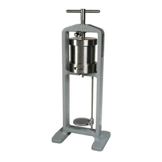
Page 32: Figure 10-6 Dead-Weight Hydraulic Assembly
LPLT Filter Press Instruction Manual Table 10-6 Dead-Weight Hydraulic Filter Press, P/N 207290 Part No. Description 207127 FILTER PRESS, BASIC ASSEMBLY 208594 DEAD-WEIGHT HYDRAULIC ASSEMBLY Figure 10-6 Dead-Weight Hydraulic Assembly 207128 Revision G, September 2012... -
Page 33: Figure 10-7 Wall Mount Filter Press W/Co Pressure Assembly
LPLT Filter Press Instruction Manual Wall Mount Filter Press Assemblies Table 10-7 Wall Mount Filter Press w/CO Pressure Assembly, P/N 207503 Part Description 205868 GRADUATED CYLINDER, 25 ml 206051 FILTER PAPER (100/BOX) 207391 FILTER PRESS, WALL MOUNT 208647 PRESSURE ASSEMBLY Figure 10-7 Wall Mount Filter Press w/CO Pressure Assembly 207128... -
Page 34: Figure 10-8 Four Unit Filter Press W/Manifold
LPLT Filter Press Instruction Manual Multiple Cell Filter Press Assemblies Table 10-8 Four Unit Filter Press with Manifold, P/N 207785 Part No. Description 205587 COUPLING, 1/4-IN. NPT 205868 GRADUATED CYLINDER, 25 ML 205889 PIPE PLUG, 1/4-IN. NPT 206051 FILTER PAPER (100/BOX) 207444 PIN FOR INSERT 207786... -
Page 35: Figure 10-9 Six Unit Filter Press W/Manifold
LPLT Filter Press Instruction Manual Table 10-9 Six Unit Filter Press with Manifold, P/N 207673 Part No. Description 205587 COUPLING, 1/4-IN. NPT 205868 GRADUATED CYLINDER, 25 ML 205889 PIPE PLUG, 1/4-IN. NPT 206051 FILTER PAPER (100/BOX) 207444 PIN FOR INSERT 207674 FRAME 207675... -
Page 36: Table 10-10 Co 2 Pressure Assembly, P/N 208647
LPLT Filter Press Instruction Manual Carbon Dioxide Pressuring Equipment Table 10-10 CO Pressure Assembly, P/N 208647 Part No. Description 208602 GAUGE, 200 PSI, 1-1/2-IN. DIA, 1/8 NPT 208612 BARREL FOR CO CARTRIDGE 208614 ADAPTER HEAD W/ PUNCTURE PIN 208615 REGULATOR 208653 SAFETY BLEEDER VALVE, 170 PSI Table 10-11 CO... -
Page 37: Table 10-14 Nitrogen Pressure Regulator, P/N 208652
LPLT Filter Press Instruction Manual Nitrogen Pressuring Equipment Table 10-14 Nitrogen Pressure Regulator, P/N 208652 Part No. Description 203950 GLAND NUT RIGHT HAND 208059 OUTLET CONNECTION 208629 CENTRALIZER 208630 DIAPHRAGM NUT 208631 DIAPHRAGM PLATE 208633 NOZZLE 208634 SEAT ASSEMBLY 208635 GASKET BUSHING REGULATOR –... -
Page 38: Warranty And Returns
11.2 Returns For your protection, items being returned must be carefully packed to prevent damage in shipment and insured against possible damage or loss. Fann will not be responsible for damage resulting from careless or insufficient packing. Before returning items for any reason, authorization must be obtained from Fann Instrument Company.