
Subscribe to Our Youtube Channel
Related Manuals for Raptor R00190

Summary of Contents for Raptor R00190
- Page 1 DIGITAL MULTIMETER With Temperature Function USER MANUAL R00190 R00193 Before using the instrument, please read this manual carefully and save for future reference.
- Page 2 Safety information Safety symbols. This symbol adjacent to another symbol, terminal or operating device indicates that the operator must refer to an explanation in the operating instructions to avoid personal injury or damage to the meter. WARNING symbol indicates a potentially hazardous situation, which if not avoided, could result in death or serious injury.
- Page 3 Safety information This symbol, adjacent to one or more terminals identifies them as being associated with ranges that may, in normal use, be subjected to particularly hazardous voltages. For maximum safety, the meter and its test leads should not be handled when these terminals are energized.
- Page 4 Maintenance Maintenance Information. • The unit may be cleaned using a dry soft cloth, do not use a wet or abrasive cloth, solvents or detergents. • Always remove any test/temperature leads when not in use. Calibration. To maintain the integrity of measurements, Wolseley recommends that the multimeter is calibrated annually at an approved Calibration Laboratory.
- Page 5 Features Accessories. • Test leads. • 9V battery. • User manual. • K Type 1m wire thermocouple & adaptor. Symbols. Continuity Low Battery Diode HOLD Data Hold Max data Hold AUTO Auto-ranging Alternating Current or Voltage Direct Current or Voltage °F Degrees Fahrenheit °C...
-
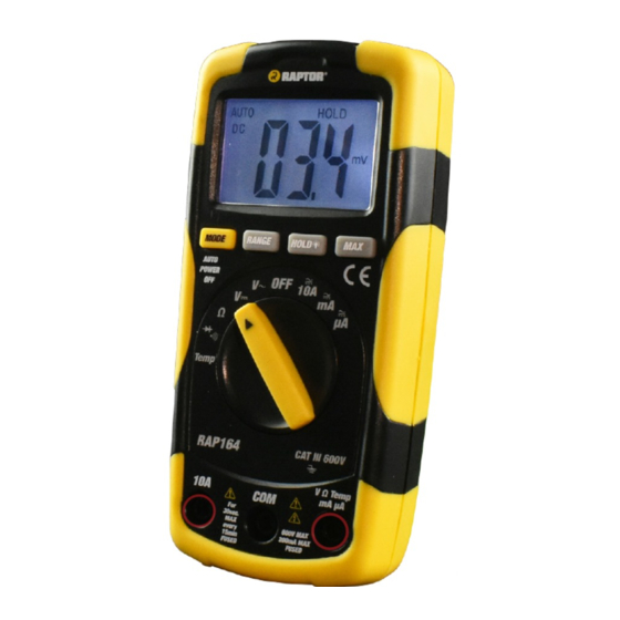
Page 6: Physical Appearance
Features Physical Appearance. Height - 140mm Weight - 208g Width - 66mm (without battery) Depth - 37mm... - Page 7 Measurement Method Measurement Method. WARNING: Risk of electrocution. High-voltage circuits, both AC and DC, are very dangerous and should be measured with great care. 1.ALWAYS turn the function switch to the OFF position when the meter is not in use. This meter has Auto OFF that automatically shuts the meter off if 15 minutes elapse between uses.
- Page 8 Measurement Method Mode Button. To select Diode/Continuity or DC/AC current, Temperature(C/F). Range Button. When the meter is first turned on, it automatically goes into Auto Ranging. This automatically selects the best range for the measurements being made and is generally the best mode for most measurements.
- Page 9 Measurement Method Data Hold/Back-light Control Button. The Data Hold function allows the meter to “freeze” a measurement for later reference and control the back light. 1. Press the Data Hold/Back-light control button to retain the reading on the indicator. The indicator “HOLD” will be appear in the display.
- Page 10 Measurement Method DC Voltage Measurements. CAUTION: Do not measure DC voltages if a motor on the circuit is being switched ON or OFF. Large voltage surges may occur that can damage the meter. 1. Set the function switch to the V DC position (“mV”...
- Page 11 Measurement Method As a result, the reading may show 0 volts when the outlet actually has voltage on it. Make sure the probe tips are touching the metal contacts inside the outlet before assuming that no voltage is present. CAUTION: Do not measure AC voltages if a motor on the circuit is being switched ON or OFF.
- Page 12 Measurement Method DC Current Measurements. CAUTION: Do not make current measurements on the 10A scale for longer than 30 seconds. Exceeding 30 seconds may cause damage to the meter and/or the test leads. 1. Insert the black test lead banana plug into the negative (COM) jack.
- Page 13 Measurement Method 6. Remove power from the circuit under test, then open up the circuit at the point where you wish to measure current. 7. Touch the black test probe tip to the negative side of the circuit. Touch the red test probe tip to the positive side of the circuit.
- Page 14 Measurement Method 1. Insert the black test lead banana plug into the negative (COM) jack. 2. For current measurements up to 2000µA AC, set the function switch to the µA position and insert the red test lead banana plug into the (µA) jack.
- Page 15 Measurement Method 9. Read the current in the display. The display will indicate the proper decimal point, value and symbol. Resistance Measurements. WARNING: To avoid electric shock, disconnect power to the unit under test and discharge all capacitors before taking any resistance measurements.
- Page 16 Measurement Method Continuity Check. WARNING: To avoid electric shock, never measure continuity on circuits or wires that have voltage on them. 1. Set the function switch to the position. 2. Insert the black lead banana plug into the negative jack (COM) and the red test lead banana plug into the positive jack (Ω).
- Page 17 Measurement Method 3. Insert the black test lead banana plug into the negative jack (COM) and the red test lead banana plug into the positive jack (Ω). 4. Touch the test probe tips to the diode or semiconductor junction you wish to test. Note the meter reading.
- Page 18 Measurement Method 1. Insert the black side of K Type adapter into the negative (COM) jack and the red side of K Type adapter into the positive (V) jack, making sure to observe the correct polarity. 2. Pressing the mode button will change temperature unit between °C/°F.
- Page 19 Battery Replacement Battery. WARNING: To avoid electric shock, disconnect the test leads from any source of voltage before removing the battery door. 1. When the batteries become exhausted or drop below the operating voltage, “BAT” will appear in the right-hand side of the LCD display. The battery should be replaced.
- Page 20 Battery Replacement 1. Disconnect the test leads from the meter. 2. Open the battery door by loosening the screw using a Phillips head screwdriver. 3. Insert the battery into battery holder, observing the correct polarity. 4. Put the battery door back in place. Secure with the two screws.
- Page 21 Fuse Replacement Replacing The Fuses. WARNING: To avoid electric shock, disconnect the test leads from any source of voltage before removing the fuse door. 1. Disconnect the test leads from the meter and any item under test. 2. Fuse can be accessed by loosening the screw on the battery door using a Phillips head screwdriver.
-
Page 22: Specification
Technical Specification. Certification EN61010-1, EN61010-2-033 Insulation Class2, Double insulation Over Voltage Category CATIII 600V Display 2000 Counts LCD display Polarity Automatic, (-) negative polarity indication Over Range OL indication Low Battery Indication BAT is displayed when battery voltage drops below the operating level Measurement Rate 2 times per second, nominal... - Page 23 Technical DC Voltage (auto-ranging). Range Resolution Accuracy 200.0m V 0.1m V ±0.5% of rdg ± 2 dgts 2.000 V 1m V ±1.0% of rdg ± 2 dgts 20.00 V 10m V 200.0 V 100m V 600 V ±1.2% of rdg ± 2 dgts Input Impedance: 10MΩ.
- Page 24 Technical AC Voltage (auto-ranging except 200mV). Range Resolution Accuracy 200.0m V 0.1m V ±1.5% of rdg ± 30 dgts 2.000 V 1m V ±1.2% of rdg ± 3 dgts 20.00 V 10m V ±1.5% of rdg ± 3 dgts 200.0 V 100m V 600 V ±2.0% of rdg ±...
- Page 25 Technical Overload protection: 0.2A/250V and 10A/250V fuse. Maximum input: 200mA DC or 200mA AC rms on uA/mA ranges, 10A DC or AC rms on 10A range. AC Current (auto-ranging for uA and mA). Range Resolution Accuracy 200.0uA 0.1uA ±1.5% of rdg ± 5 dgts 2000uA ±1.8% of rdg ±...
- Page 26 Technical Resistance (auto-ranging). Range Resolution Accuracy 200.0Ω 0.1Ω ±1.2% of rdg ± 4 dgts 2.000KΩ 1Ω ±1.0% of rdg ± 2 dgts 20.00KΩ 10Ω ±1.2% of rdg ± 2 dgts 200.0KΩ 100Ω 2.000MΩ 1KΩ 20.00MΩ 10KΩ ±2.0% of rdg ± 3 dgts Input protection: 250V.
-
Page 27: Audible Continuity
Technical Audible continuity. Audible threshold: Less than 100Ω. Test current: <0.3mA. Overload protection: 250V DC or AC rms. Temperature. Range Resolution Accuracy -50°C~+1000°C 1°C ±3% of rdg ± 5 dgts -58°F~+1832°F 1°F ±3% of rdg ± 8 dgts Sensor: Type K Thermocouple. Overload protection: 250V DC or AC rms. - Page 28 Limited warranty 1 year warranty against any manufacturing defects or faulty workmanship. This warranty does not cover fuses, disposable batteries or damage from accident, neglect, misuse, alteration, contamination or abnormal conditions of operation or handling. WEEE Directive 2012/19/EU At the end of the product life, dispose of the instrument &...
Need help?
Do you have a question about the R00190 and is the answer not in the manual?
Questions and answers