Table of Contents
Advertisement
Quick Links
Advertisement
Table of Contents

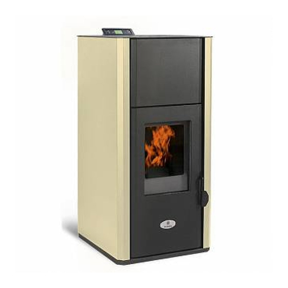
Summary of Contents for Termal Kamin 20
- Page 1 SERVICE MANUAL SERVICE OF PELLET BOILERS AND STOVES...
-
Page 2: Table Of Contents
Service manual CONTENT INTRODUCTION ..................................3 ELECTROMECHANICAL PARTS ..............................4 Sensors – senses ................................4 2.1.1 TC themperature sensor ............................4 2.1.2 NTC themperature sensor ............................. 4 2.1.3 Pressure switch ..............................5 2.1.4 Inductive position sensor ............................6 2.1.5 Microswitch ................................6 2.1.6 Thermostat ................................ -
Page 3: Introduction
Service manual 1 INTRODUCTION The document presented before you is a manual for the product service (stoves and boilers) of d.o.o. In this connection, the document contains brief descriptions of individual product lines, working principles and basic components of the automatic regulation of the pellet combustion process. -
Page 4: Electromechanical Parts
Service manual 2 ELECTROMECHANICAL PARTS In order for the control unit to manage the pellet combustion process, it has to have properly set up and functional components that can be divided into two basic groups: 2.1 Sensors – senses 2.1.1 TC themperature sensor The sensor is intended for reading the temperature of the exhaust gases. -
Page 5: Pressure Switch
Service manual sensor in the form of a cylindrical thickening is placed at the bottom of the tube only so that it makes contact with the copper surface. Attention should be paid when mounting the boiler liner so that the sensor does not move from the original position. -
Page 6: Inductive Position Sensor
Service manual 2.1.4 Inductive position sensor An inductive position sensor is a contactless sensor that has the ability to detect metal near the sensing head (about 2mm / max 4mm in front of the head surface). It is only installed in smart boilers and is an integral part of the mechanism of the mechanism with "self-cleaning burners". -
Page 7: Thermostat
Service manual 2.1.6 Thermostat The thermostat is a safety switch for the temperature of the liquid in the boiler. It performs the function of protecting the device (boiler / fireplace), the central heating system or people and objects that are located close to the boiler and heating installation due to overheating and the formation of a fire when the boiler temperature is exceeded. -
Page 8: Actuators - Executive Devices
Service manual 2.2 Actuators - executive devices 2.2.1 Heater The heater is a device by which the incineration of the pellet or the first pellet dose in the burner is carried out. In all stoves and boilers, in addition to some industrial ones, identical 250W heaters are installed. -
Page 9: Dispenser-Auger Assembly
Service manual They have the function of removing heat from the warm surfaces of the stove and using the directional air to pass it over to the room. Its work can define a control unit in a way that automatically increases the speed of rotation in relation to the achieved temperature of the stove or that the user sets the fixed speed of rotation. -
Page 10: Water Pump
Service manual 2.2.4 Water pump The pump is a device that enables or initiates the flow of liquids through the central heating system. In the KAMIN series and boilers up to 25kW, the factory is built into the boilers together with the expansion vessel and the safety valve. - Page 11 Service manual Important note: In the middle of 2021, an improved version of the ALPHA75_V2 controller was implemented. The mentioned controller changes the previously used ones (Alpha65 and Alpha75). The following has been replaced: 1. The fuse is no longer on the electronics but on the Euro socket where the power cord is plugged 2.
- Page 12 Service manual How to recognize the Upgrade Controller: The boiler on which the controller has been changed can be checked by looking at the declaration from the boiler and at end of the serial number it will say -V2 Example in the picture below:...
- Page 13 Service manual SIMPLE/STANDARD:...
- Page 14 Service manual KAMIN/COMPACT/SM_ECO 35 kW:...
- Page 15 Service manual SM ECO 50 – 70 kW ,with only one fan (smoke extraction):...
- Page 16 Service manual SM ECO 50 – 70 kW , with two fans primar air and smoke extraction):...
- Page 17 Service manual SM ECO 50 – 70 kW with dosing auger overheat protection:...
- Page 18 Service manual...
- Page 19 Service manual SM ECO 100kW and higher:...
- Page 20 Service manual...
-
Page 21: Programming Boilers With A Manual Unit
Service manual 4 PROGRAMMING BOILERS WITH A MANUAL UNIT For the programming of boiler control units in the field, a handy device is used so-called. "Manual programmer". It contains the complete programs necessary for programming various boiler models produced by the company d.o.o. - Page 22 Service manual For example, we want to program the boiler with the program according to the list of programmers 02. We connect the programmer, blink our first tag ..to UP we select the folder 02. Press the ENTER button to select this folder, blink the second mark 01.
-
Page 23: Service Settings
Service manual 5 SERVICE SETTINGS The boiler from the factory is delivered with a program of pre-defined operating parameters which after manual change can no longer be easily returned to the factory settings except for reprogramming, so do not change the operating parameter if it really is not necessary. The service menu is locked to prevent access to unskilled curious people. - Page 24 Service manual After that, the following screen will appear Click on the ENTER button. We'll get four numbers. (numbers are randomly generated, that is, with each unlock, there will be other numbers) It is necessary to collect four numbers and increase their sum by one. In our case: 3 + 4 + 2 + 4 = 13 and when 1 is added, the result is 14.
-
Page 25: Setting Operating Parameters
Service manual Use the button (+) increase the number to the value of the results (14) Then, pressing ENTER again, we will see the next display: By this we unlocked the service menu and now we can perform certain checks or modifications. The service menu will be locked again after half an hour of inactive operation or if the control unit is reset to the main switch located on the back of the boiler. -
Page 26: Other Settings In The Service Menu
Service manual Clicking again ENTER will show the zero parameter parameter P000, the (+) and (-) keys are selected which parameter we want from P000 to P0105. After that, pressing ENTER will show the value of the parameter, which we increase or decrease with the (+) and (-) keys. After the correct value is set, pressing the ENTER key will save the parameter value. -
Page 27: First Ignition Of The Boiler
Service manual individual outputs regulation are set from 0-255 [12] ----- Reading interval of ------- operation, the ignition, turning off the boiler, etc. [13] Logs ----- ------- ------- 6 First ignition of the boiler The boiler must be inspected and commissioned by an authorized service technician only so that the guarantee for the boiler is valid. - Page 28 Service manual...
- Page 29 Service manual...
-
Page 30: Sample Of Factory-Performance Parameters
Service manual 7 A sample of factory-PERFORMANCE PARAMETERS It is important to note that the values of the operating parameters differ in both the types of boiler series, their power, and the types of burners and motors of the dispenser. The servicer is obliged, before any correction of the working parameters, to determine which construction is a burner and a dispenser assembly (motor + spiral). - Page 31 Service manual Parameters: 0. Fuel ignition timeout --> [15] 1. Ignition test timeout --> [10] 2. Fuel type --> [0] 3. Heat up feeder OFF time --> [10] 4. Heat up feeder ON time --> [230] 5. Fuel ignition feeder 1 OFF time --> [130] 6.
- Page 32 Service manual 26. Power 3 fan 1 speed --> [125] 27. Power 4 fan 1 speed --> [123] 28. Power 5 fan 1 speed --> [123] 29. Test fire fan 2 speed --> [0] 30. Stop fire fan 2 speed --> [220] 31.
- Page 33 Service manual 53. Cool fluid entry temp. diff. --> [10] 54. Ignition test gases temperature --> [70] 55. Modulation start gases temperature --> [510] 56. Heating device OFF gases temperature --> [65] 57. Maximum (error) gases temperature --> [510] 58. Fan 2 as ambient min. gases temp. --> [70] 59.
- Page 34 Service manual 80. Flame OFF detection delay --> [0] 81. Underpressure setpoint --> [0] 82. Min. (error) underpressure/airflow --> [0] 83. Underpressure/airflow error delay --> [0] 84. Accumulator temperature --> [0] 85. T1-T2 for water pump OFF --> [0] 86. Boiler to accu. temperature drop --> [0] 87.
-
Page 35: Edge / Comfy 10 Kw
Service manual 7.2 EDGE / COMFY 10 kW Design type of burner and gear motor pellet dispenser: Has to be : 4.4 rpm... - Page 36 Service manual Parameters: 0. Fuel ignition timeout --> [20] 1. Ignition test timeout --> [15] 2. Fuel type --> [0] 3. Heat up feeder OFF time --> [10] 4. Heat up feeder ON time --> [150] 5. Fuel ignition feeder 1 OFF time --> [150] 6.
- Page 37 Service manual 26. Power 3 fan 1 speed --> [154] 27. Power 4 fan 1 speed --> [156] 28. Power 5 fan 1 speed --> [159] 29. Test fire fan 2 speed --> [0] 30. Stop fire fan 2 speed --> [0] 31.
- Page 38 Service manual 53. Cool fluid entry temp. diff. --> [0] 54. Ignition test gases temperature --> [55] 55. Modulation start gases temperature --> [250] 56. Heating device OFF gases temperature --> [50] 57. Maximum (error) gases temperature --> [250] 58. Fan 2 as ambient min. gases temp. --> [120] 59.
- Page 39 Service manual 80. Flame OFF detection delay --> [2] 81. Underpressure setpoint --> [0] 82. Min. (error) underpressure/airflow --> [0] 83. Underpressure/airflow error delay --> [0] 84. Accumulator temperature --> [0] 85. T1-T2 for water pump OFF --> [0] 86. Boiler to accu. temperature drop --> [0] 87.
-
Page 40: Kamin / Exclusive / Edge 15 Kw
Service manual 7.3 KAMIN / EXCLUSIVE / EDGE 15 kW Design type of burner and gear motor pellet dispenser Has to be : 4.4 rpm... - Page 41 Service manual Parameters 0. Fuel ignition timeout --> [20] 1. Ignition test timeout --> [15] 2. Fuel type --> [0] 3. Heat up feeder OFF time --> [200] 4. Heat up feeder ON time --> [200] 5. Fuel ignition feeder 1 OFF time --> [150] 6.
- Page 42 Service manual 26. Power 3 fan 1 speed --> [154] 27. Power 4 fan 1 speed --> [156] 28. Power 5 fan 1 speed --> [159] 29. Test fire fan 2 speed --> [0] 30. Stop fire fan 2 speed --> [0] 31.
- Page 43 Service manual 53. Cool fluid entry temp. diff. --> [0] 54. Ignition test gases temperature --> [50] 55. Modulation start gases temperature --> [250] 56. Heating device OFF gases temperature --> [48] 57. Maximum (error) gases temperature --> [250] 58. Fan 2 as ambient min. gases temp. --> [120] 59.
- Page 44 Service manual 80. Flame OFF detection delay --> [2] 81. Underpressure setpoint --> [0] 82. Min. (error) underpressure/airflow --> [0] 83. Underpressure/airflow error delay --> [0] 84. Accumulator temperature --> [0] 85. T1-T2 for water pump OFF --> [0] 86. Boiler to accu. temperature drop --> [0] 87.
-
Page 45: Kamin / Exlusive 20 Kw
Service manual 7.4 KAMIN / EXLUSIVE 20 kW Design type of burner and gear motor pellet dispenser Has to be : 4.4 rpm... - Page 46 Service manual Parameters 0. Fuel ignition timeout --> [20] 1. Ignition test timeout --> [15] 2. Fuel type --> [0] 3. Heat up feeder OFF time --> [200] 4. Heat up feeder ON time --> [200] 5. Fuel ignition feeder 1 OFF time --> [150] 6.
- Page 47 Service manual 26. Power 3 fan 1 speed --> [154] 27. Power 4 fan 1 speed --> [156] 28. Power 5 fan 1 speed --> [159] 29. Test fire fan 2 speed --> [0] 30. Stop fire fan 2 speed --> [0] 31.
- Page 48 Service manual 53. Cool fluid entry temp. diff. --> [0] 54. Ignition test gases temperature --> [50] 55. Modulation start gases temperature --> [250] 56. Heating device OFF gases temperature --> [48] 57. Maximum (error) gases temperature --> [250] 58. Fan 2 as ambient min. gases temp. --> [120] 59.
- Page 49 Service manual 80. Flame OFF detection delay --> [2] 81. Underpressure setpoint --> [0] 82. Min. (error) underpressure/airflow --> [0] 83. Underpressure/airflow error delay --> [0] 84. Accumulator temperature --> [0] 85. T1-T2 for water pump OFF --> [0] 86. Boiler to accu. temperature drop --> [0] 87.
-
Page 50: Kotao Edge 23 Kw
Service manual 7.5 KOTAO EDGE 23 kW Design type of burner and gear motor pellet dispenser Has to be : 4.4 rpm... - Page 51 Service manual Parameters 0. Fuel ignition timeout --> [20] 1. Ignition test timeout --> [15] 2. Fuel type --> [0] 3. Heat up feeder OFF time --> [200] 4. Heat up feeder ON time --> [200] 5. Fuel ignition feeder 1 OFF time --> [150] 6.
- Page 52 Service manual 26. Power 3 fan 1 speed --> [154] 27. Power 4 fan 1 speed --> [156] 28. Power 5 fan 1 speed --> [159] 29. Test fire fan 2 speed --> [0] 30. Stop fire fan 2 speed --> [0] 31.
- Page 53 Service manual 53. Cool fluid entry temp. diff. --> [0] 54. Ignition test gases temperature --> [50] 55. Modulation start gases temperature --> [250] 56. Heating device OFF gases temperature --> [47] 57. Maximum (error) gases temperature --> [250] 58. Fan 2 as ambient min. gases temp. --> [120] 59.
- Page 54 Service manual 80. Flame OFF detection delay --> [2] 81. Underpressure setpoint --> [0] 82. Min. (error) underpressure/airflow --> [0] 83. Underpressure/airflow error delay --> [0] 84. Accumulator temperature --> [0] 85. T1-T2 for water pump OFF --> [0] 86. Boiler to accu. temperature drop --> [0] 87.
-
Page 55: Kamin / Compact 25 Kw
Service manual 7.6 KAMIN / COMPACT 25 kW Design type of burner and gear motor pellet dispenser Has to be : 4.4 rpm... - Page 56 Service manual Parameters 0. Fuel ignition timeout --> [20] 1. Ignition test timeout --> [15] 2. Fuel type --> [0] 3. Heat up feeder OFF time --> [200] 4. Heat up feeder ON time --> [200] 5. Fuel ignition feeder 1 OFF time --> [150] 6.
- Page 57 Service manual 26. Power 3 fan 1 speed --> [154] 27. Power 4 fan 1 speed --> [156] 28. Power 5 fan 1 speed --> [159] 29. Test fire fan 2 speed --> [0] 30. Stop fire fan 2 speed --> [0] 31.
- Page 58 Service manual 53. Cool fluid entry temp. diff. --> [0] 54. Ignition test gases temperature --> [50] 55. Modulation start gases temperature --> [250] 56. Heating device OFF gases temperature --> [47] 57. Maximum (error) gases temperature --> [250] 58. Fan 2 as ambient min. gases temp. --> [120] 59.
- Page 59 Service manual 80. Flame OFF detection delay --> [2] 81. Underpressure setpoint --> [0] 82. Min. (error) underpressure/airflow --> [0] 83. Underpressure/airflow error delay --> [0] 84. Accumulator temperature --> [0] 85. T1-T2 for water pump OFF --> [0] 86. Boiler to accu. temperature drop --> [0] 87.
-
Page 60: Smart 25Kw
Service manual 7.7 SMART 25kW Design type of burner and gear motor pellet dispenser: Has to be : 4.4 rpm... - Page 61 Service manual Parameters 0. Fuel ignition timeout --> [20] 1. Ignition test timeout --> [15] 2. Fuel type --> [0] 3. Heat up feeder OFF time --> [250] 4. Heat up feeder ON time --> [150] 5. Fuel ignition feeder 1 OFF time --> [150] 6.
- Page 62 Service manual 26. Power 3 fan 1 speed --> [172] 27. Power 4 fan 1 speed --> [175] 28. Power 5 fan 1 speed --> [180] 29. Test fire fan 2 speed --> [0] 30. Stop fire fan 2 speed --> [0] 31.
- Page 63 Service manual 53. Cool fluid entry temp. diff. --> [0] 54. Ignition test gases temperature --> [55] 55. Modulation start gases temperature --> [255] 56. Heating device OFF gases temperature --> [50] 57. Maximum (error) gases temperature --> [255] 58. Fan 2 as ambient min. gases temp. --> [255] 59.
- Page 64 Service manual 80. Flame OFF detection delay --> [5] 81. Underpressure setpoint --> [0] 82. Min. (error) underpressure/airflow --> [0] 83. Underpressure/airflow error delay --> [0] 84. Accumulator temperature --> [0] 85. T1-T2 for water pump OFF --> [0] 86. Boiler to accu. temperature drop --> [0] 87.
-
Page 65: Smart 33 Kw
Service manual 7.8 SMART 33 kW Design type of burner and gear motor pellet dispenser Has to be : 4.4 rpm... - Page 66 Service manual Parameters 0. Fuel ignition timeout --> [20] 1. Ignition test timeout --> [15] 2. Fuel type --> [0] 3. Heat up feeder OFF time --> [250] 4. Heat up feeder ON time --> [250] 5. Fuel ignition feeder 1 OFF time --> [150] 6.
- Page 67 Service manual 26. Power 3 fan 1 speed --> [185] 27. Power 4 fan 1 speed --> [190] 28. Power 5 fan 1 speed --> [195] 29. Test fire fan 2 speed --> [0] 30. Stop fire fan 2 speed --> [0] 31.
- Page 68 Service manual 53. Cool fluid entry temp. diff. --> [0] 54. Ignition test gases temperature --> [55] 55. Modulation start gases temperature --> [255] 56. Heating device OFF gases temperature --> [50] 57. Maximum (error) gases temperature --> [255] 58. Fan 2 as ambient min. gases temp. --> [255] 59.
- Page 69 Service manual 80. Flame OFF detection delay --> [5] 81. Underpressure setpoint --> [0] 82. Min. (error) underpressure/airflow --> [0] 83. Underpressure/airflow error delay --> [0] 84. Accumulator temperature --> [0] 85. T1-T2 for water pump OFF --> [0] 86. Boiler to accu. temperature drop --> [0] 87.
-
Page 70: Compact 33 Kw
Service manual 7.9 COMPACT 33 kW Design type of burner and gear motor pellet dispenser Has to be : 4.4 rpm... - Page 71 Service manual Parameters 0. Fuel ignition timeout --> [20] 1. Ignition test timeout --> [15] 2. Fuel type --> [0] 3. Heat up feeder OFF time --> [200] 4. Heat up feeder ON time --> [200] 5. Fuel ignition feeder 1 OFF time --> [150] 6.
- Page 72 Service manual 26. Power 3 fan 1 speed --> [180] 27. Power 4 fan 1 speed --> [190] 28. Power 5 fan 1 speed --> [200] 29. Test fire fan 2 speed --> [0] 30. Stop fire fan 2 speed --> [0] 31.
- Page 73 Service manual 53. Cool fluid entry temp. diff. --> [0] 54. Ignition test gases temperature --> [55] 55. Modulation start gases temperature --> [255] 56. Heating device OFF gases temperature --> [60] 57. Maximum (error) gases temperature --> [255] 58. Fan 2 as ambient min. gases temp. --> [200] 59.
- Page 74 Service manual 80. Flame OFF detection delay --> [2] 81. Underpressure setpoint --> [0] 82. Min. (error) underpressure/airflow --> [0] 83. Underpressure/airflow error delay --> [0] 84. Accumulator temperature --> [0] 85. T1-T2 for water pump OFF --> [0] 86. Boiler to accu. temperature drop --> [0] 87.
-
Page 75: Combo 35 Kw
Service manual 7.10 COMBO 35 kW Design type of burner and gear motor pellet dispenser Has to be : 4.4 rpm... - Page 76 Service manual Parameters 0. Fuel ignition timeout --> [20] 1. Ignition test timeout --> [15] 2. Fuel type --> [0] 3. Heat up feeder OFF time --> [200] 4. Heat up feeder ON time --> [200] 5. Fuel ignition feeder 1 OFF time --> [200] 6.
- Page 77 Service manual 26. Power 3 fan 1 speed --> [140] 27. Power 4 fan 1 speed --> [150] 28. Power 5 fan 1 speed --> [160] 29. Test fire fan 2 speed --> [0] 30. Stop fire fan 2 speed --> [0] 31.
- Page 78 Service manual 53. Cool fluid entry temp. diff. --> [0] 54. Ignition test gases temperature --> [55] 55. Modulation start gases temperature --> [255] 56. Heating device OFF gases temperature --> [50] 57. Maximum (error) gases temperature --> [255] 58. Fan 2 as ambient min. gases temp. --> [200] 59.
- Page 79 Service manual 80. Flame OFF detection delay --> [2] 81. Underpressure setpoint --> [0] 82. Min. (error) underpressure/airflow --> [0] 83. Underpressure/airflow error delay --> [0] 84. Accumulator temperature --> [0] 85. T1-T2 for water pump OFF --> [0] 86. Boiler to accu. temperature drop --> [0] 87.
-
Page 80: Sm Eco 35 Kw
Service manual 7.11 SM ECO 35 kW Design type of burner and gear motor pellet dispenser Has to be : 4.4 rpm... - Page 81 Service manual Parameters 0. Fuel ignition timeout --> [20] 1. Ignition test timeout --> [15] 2. Fuel type --> [0] 3. Heat up feeder OFF time --> [200] 4. Heat up feeder ON time --> [200] 5. Fuel ignition feeder 1 OFF time --> [200] 6.
- Page 82 Service manual 26. Power 3 fan 1 speed --> [150] 27. Power 4 fan 1 speed --> [160] 28. Power 5 fan 1 speed --> [170] 29. Test fire fan 2 speed --> [0] 30. Stop fire fan 2 speed --> [0] 31.
- Page 83 Service manual 53. Cool fluid entry temp. diff. --> [0] 54. Ignition test gases temperature --> [55] 55. Modulation start gases temperature --> [255] 56. Heating device OFF gases temperature --> [60] 57. Maximum (error) gases temperature --> [255] 58. Fan 2 as ambient min. gases temp. --> [200] 59.
- Page 84 Service manual 80. Flame OFF detection delay --> [2] 81. Underpressure setpoint --> [0] 82. Min. (error) underpressure/airflow --> [0] 83. Underpressure/airflow error delay --> [0] 84. Accumulator temperature --> [0] 85. T1-T2 for water pump OFF --> [0] 86. Boiler to accu. temperature drop --> [0] 87.
-
Page 85: Sm Eco 50 Kw
Service manual 7.12 SM ECO 50 kW Design type of burner and gear motor pellet dispenser Has to be : 4.4 rpm... - Page 86 Service manual Parameters 0. Fuel ignition timeout --> [30] 1. Ignition test timeout --> [15] 2. Fuel type --> [0] 3. Heat up feeder OFF time --> [100] 4. Heat up feeder ON time --> [200] 5. Fuel ignition feeder 1 OFF time --> [200] 6.
- Page 87 Service manual 26. Power 3 fan 1 speed --> [165] 27. Power 4 fan 1 speed --> [165] 28. Power 5 fan 1 speed --> [160] 29. Test fire fan 2 speed --> [170] 30. Stop fire fan 2 speed --> [170] 31.
- Page 88 Service manual 53. Cool fluid entry temp. diff. --> [0] 54. Ignition test gases temperature --> [60] 55. Modulation start gases temperature --> [255] 56. Heating device OFF gases temperature --> [55] 57. Maximum (error) gases temperature --> [255] 58. Fan 2 as ambient min. gases temp. --> [10] 59.
- Page 89 Service manual 80. Flame OFF detection delay --> [0] 81. Underpressure setpoint --> [200] 82. Min. (error) underpressure/airflow --> [0] 83. Underpressure/airflow error delay --> [0] 84. Accumulator temperature --> [0] 85. T1-T2 for water pump OFF --> [0] 86. Boiler to accu. temperature drop --> [0] 87.
-
Page 90: Sm Eco 70 Kw
Service manual 7.13 SM ECO 70 kW Design type of burner and gear motor pellet dispenser Has to be : 4.4 rpm... - Page 91 Service manual Parameters 0. Fuel ignition timeout --> [30] 1. Ignition test timeout --> [20] 2. Fuel type --> [0] 3. Heat up feeder OFF time --> [100] 4. Heat up feeder ON time --> [200] 5. Fuel ignition feeder 1 OFF time --> [150] 6.
- Page 92 Service manual 26. Power 3 fan 1 speed --> [165] 27. Power 4 fan 1 speed --> [165] 28. Power 5 fan 1 speed --> [160] 29. Test fire fan 2 speed --> [180] 30. Stop fire fan 2 speed --> [80] 31.
- Page 93 Service manual 53. Cool fluid entry temp. diff. --> [0] 54. Ignition test gases temperature --> [60] 55. Modulation start gases temperature --> [255] 56. Heating device OFF gases temperature --> [55] 57. Maximum (error) gases temperature --> [255] 58. Fan 2 as ambient min. gases temp. --> [10] 59.
- Page 94 Service manual 80. Flame OFF detection delay --> [0] 81. Underpressure setpoint --> [200] 82. Min. (error) underpressure/airflow --> [0] 83. Underpressure/airflow error delay --> [0] 84. Accumulator temperature --> [0] 85. T1-T2 for water pump OFF --> [0] 86. Boiler to accu. temperature drop --> [0] 87.
-
Page 95: Sm Eco 100 Kw
Service manual 7.14 SM ECO 100 kW Design type of burner and gear motor pellet dispenser Has to be : 4.4 rpm... - Page 96 Service manual Parameters 0. Fuel ignition timeout --> [30] 1. Ignition test timeout --> [20] 2. Fuel type --> [0] 3. Heat up feeder OFF time --> [200] 4. Heat up feeder ON time --> [200] 5. Fuel ignition feeder 1 OFF time --> [150] 6.
- Page 97 Service manual 26. Power 3 fan 1 speed --> [145] 27. Power 4 fan 1 speed --> [145] 28. Power 5 fan 1 speed --> [145] 29. Test fire fan 2 speed --> [220] 30. Stop fire fan 2 speed --> [180] 31.
- Page 98 Service manual 53. Cool fluid entry temp. diff. --> [0] 54. Ignition test gases temperature --> [85] 55. Modulation start gases temperature --> [255] 56. Heating device OFF gases temperature --> [80] 57. Maximum (error) gases temperature --> [255] 58. Fan 2 as ambient min. gases temp. --> [10] 59.
- Page 99 Service manual 80. Flame OFF detection delay --> [0] 81. Underpressure setpoint --> [200] 82. Min. (error) underpressure/airflow --> [0] 83. Underpressure/airflow error delay --> [0] 84. Accumulator temperature --> [0] 85. T1-T2 for water pump OFF --> [0] 86. Boiler to accu. temperature drop --> [0] 87.