Table of Contents
Advertisement
Quick Links
GENERAL INFORMATION
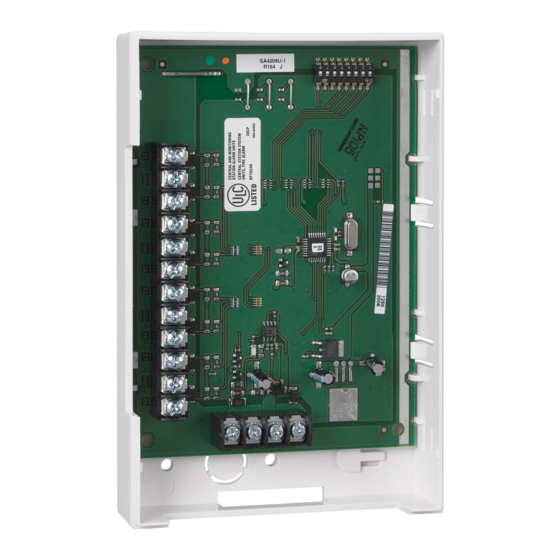
The ADEMCO 4208U is a V-Plex
with ADEMCO controls that support V-Plex (polling loop) devices.
Characteristics of this device include:
Can be optionally powered from the control panel aux. power
•
supply to reduce the amount of current draw from the polling
loop. NOTE: The 4208U cannot be used with an external
power supply for commercial fire applications.
Uniquely identifies 8 EOLR supervised zones (all zones use
•
10k resistors, supplied).
DIP Switches can be used to set zone numbers or serial
•
numbers.
When used in the serial number mode, each serial number in
•
the selected group can be assigned to any zone number.
Loops A & B can be programmed for fast (10msec) response.
•
Tamper protected.
•
1. For all fire (NFPA) and UL Commercial Burglary
installations, the 4208U must be tamper protected or
mounted in a tamper-protected cabinet.
2. Refer to the control panel installation instructions for
specific programming/installation requirements.
U L
3. All circuits are supervised and power-limited.
4. Use only 14-22 AWG wire.
5. Close contact type initiating devices.
6. All zones are Class B, Style B.
7. Voltage rating all zones: 11VDC max., 1.5mA max.
MOUNTING
1. Power should be disconnected before proceeding.
2.
Be sure to mount the 4208U before making any wiring
connections.
When mounted remotely, tamper protection is required. Holes on
the back of the module's housing permit it to be mounted
horizontally or vertically.
Wires can exit from the side or the
breakout on the back of the housing. To enable tamper protection,
set DIP Switch 8 to OFF and attach the tamper magnet (provided)
(Figure 1) to the module inside cover.
expansion zone tamper option at the control (program field 724 =
0). If the module's cover is removed, the magnet attached to the
cover (positioned near the reed switch) will cause a tamper signal
to be sent to the control for every active zone on the 4208U
module. When the installation is complete, install the cover and
affix the Serial Number and Zone Assignment Tables to the inside
cover of the control.
When mounted inside the cabinet with the control, the 4208U
should be mounted horizontally and does not need tamper
protection, provided the cabinet is supervised. Insert two screws
into the raised metal tabs leaving the heads app. 1/8" exposed,
and then hang the 4208U using the two slots on the back.
WIRING
For CE installations ADEMCO N6361 EMI suppression
C E
bead is required.
Instructions for wire routing instructions.
Polling loop and protection loop wires can be brought in either
through the back or front of the unit by removing the knockouts.
Use 22 gauge twisted pair wire for polling loop connections. All
protection loops use 10k EOL resistors (included). A maximum
resistance of 300 ohms is allowed on protection loops (excluding
EOLR). See Figure 2 for all connections.
Keep in mind that connections to the polling loop are always
required, while power supply connections are optional.
Installation and Setup Guide
®
eight-zone expander for use
Be sure to enable the
Refer to the N6361 Installation
Universal V-Plex
Figure 1. Tamper Magnet Installation
DIP SWITCH SETTINGS
Serial Number Mode:
In the serial number mode, the DIP Switches on the 4208U are used
to assign the unit to a group of 8 serial numbers. You can assign any
serial number to any zone number (except hardwire zone numbers of
the control) and you do not lose zone numbers if you don't use all
eight loops on the 4208U. Follow steps below using Table 2 for DIP
Switch settings.
Zone Assignment Mode:
In the zone assignment mode, the DIP Switches on the 4208U are
used to assign the unit to a group of 8 consecutive zones. These
zone numbers, once designated for the 4208U, cannot be used for
anything else, even if you don't use all 8. Follow the steps below
using Table 1 for DIP Switch settings.
Note: Zone Assignment Mode should only be used on panels that
DO NOT support Serial Mode.
DIP Switches
REED (TAMPER) SWITCH
TB1
1
2
3
4
5
6
7
8
10k 10k
10k 10k
10k 10k
LOOPS: A
B
C
D
E
Figure 2. Summary of Connections
Note: For Commercial and Residential Fire installations, no more than
one (1) wire per terminal may be connected.
ON
POSITION 1:
POSITIONS 2-5: SELECT THE 8 SENSOR
POSITION 6:
POSITION 7:
OFF
ON
POSITION 8:
SIDE VIEW
Figure 3. DIP Switch Settings
ADEMCO 4208U
®
Eight Zone Expander
1. INSERT BOTTOM TABS FIRST.
2. ENGAGE TOP WITH CLIP.
4208U
TB2
( ) GND
4
OPTIONAL AUX.
POWER INPUT.
SEE NOTE 1.
3
(+) 12V
2
( )
TO POLLING LOOP
(USE TWISTED PAIR)
1
(+)
NOTES:
1.
IF USING AUXILIARY POWER ON COMMECRICAL
FIRE/BURG COMBINATION SYSTEMS
(e.g. VISTA-128FBP), DO NOT CONNECT THE
POLLING LOOP GROUND ON TERMINAL 2.
9
10
11
12
AUXILIARY POWER CAN ONLY BE USED IN
BURGLARY APPLICATIONS.
2.
FOR CE INSTALLATIONS A N6363 EMI
SUPPRESSION BEAD IS REQUIRED.
(EACH LOOP'S MAX
RESISTANCE:
10k 10k
300 ohms + 10k EOLR)
F
G
H
SELECT RESPONSE TIME
FOR LOOPS A and B
(SHOWN ON = SLOW).
DEVICE GROUP ADDRESS
(SHOWN ON, ON, ON,
OFF = 2nd GROUP SELECTION).
DEVICE TYPE (SHOWN
ON = "SERIAL NUMBER MODE").
NORMALLY SET TO "OFF"
SELECT TAMPER PROTECTION
SETTING (SHOWN
"OFF" = TAMPER ENABLED).
4208U-SOC-V0
Advertisement
Table of Contents

Summary of Contents for Honeywell Home ADEMCO 4208U
- Page 1 Eight Zone Expander Installation and Setup Guide GENERAL INFORMATION ® The ADEMCO 4208U is a V-Plex eight-zone expander for use with ADEMCO controls that support V-Plex (polling loop) devices. Characteristics of this device include: Can be optionally powered from the control panel aux. power •...
- Page 2 Table 1. 4208U Zone Assignments For “Zone Assignment” mode, DIP Switch position 6 must be off. When using this mode, program each zone’s “Input Type” as “DIP Switch Polling Loop Device” (DP), where applicable. THIS SWITCH SETTING PRESETS THE LOOPS TO THESE ZONE NUMBERS DIP Switch Position Loop Designations (“-”...
- Page 3 When prompted to learn the serial number for a particular zone, Set the DIP switches on the 4208U as instructed below (see you may either enter it manually through the keypad, through Figure 3): COMPASS Downloader, or “learn” it by momentarily faulting Select fast/slow response for loops A and B using DIP Switch (shorting) the terminals of that zone as required by the control.
- Page 4 For the latest warranty information, please go to: www.security.honeywellhome.com/warranty The Honeywell Home Trademark is used under license from Honeywell International Inc. This product manufactured by Resideo Technologies and its affiliates 2 Corporate Center Drive, Suite 100 P.O. Box 9040, Melville, NY 11747 ©...
Need help?
Do you have a question about the ADEMCO 4208U and is the answer not in the manual?
Questions and answers