Table of Contents
Advertisement
Advertisement
Table of Contents

Summary of Contents for Seeing Machines Guardian
- Page 1 FIELD SUPPORT MANUAL Guardian - Generation 2 (Gen2)
- Page 2 The purpose of this manual is to describe the process for the installation, fault finding and maintenance of Guardian - Generation 2 (Gen 2). Please refer to the Guardian Field Installation Manual (June 2016) for installations of the Guardian Gen 1.
- Page 3 Guardian Field Support Manual 2. SECTIONS SECTION TITLE Preface and Compliance Certificates Introduction to Guardian Gen 2 Installation of Guardian Gen 2 Service & Maintenance of Guardian Gen 2...
- Page 4 Guardian Field Support Manual 3. REFERENCE DOCUMENTS The below referenced documents can be accessed via the Technical Communication Portal (TCP) at tcp.seeingmachines.com if you require access to the TCP, please make a request via the ‘Apply Here’ button on the TCP website.
- Page 5 FCC Part 15 Digital Emissions Compliance We, Seeing Machines, Level 1, 11 Lonsdale St, Braddon, ACT, 2612, Australia, +61 2 6103 4700, declare under our sole responsibility that the product Guardian complies with Part 15 of the FCC Rules.
- Page 6 Guardian Field Support Manual 5. Canada Certification This device complies with Industry Canada’s licence-exempt RSSs. Operation is subject to the following two conditions: (1) This device may not cause interference; and (2) This device must accept any interference, including interference that may cause undesired operation of the device.
- Page 7 FIELD SUPPORT MANUAL Section 1 – Introduction to Guardian Generation 2...
- Page 8 Guardian Field Support Manual Table of Contents OVERVIEW ............................3 ABBREVIATIONS ..........................4 TERMS ............................. 7 SAFETY ............................. 9 PACKAGING ........................... 10 STANDARD COMPONENTS ......................12 OPTIONAL COMPONENTS ..............Error! Bookmark not defined. INSTALLATION TOOL KIT (Provided by Trainer) ................19...
- Page 9 Guardian Field Support Manual 1. OVERVIEW The aim of this section is to introduce the acronyms, and components of Guardian Generation 2 (Gen 2) Section 1 A certified Guardian Technician must read and understand this section before commencing a physical installation of the System.
- Page 10 Guardian Field Support Manual 2. ABBREVIATIONS ABBREVIATION MEANING Access Point Name-Relates to SIM Card Cellular CELL -Wireless communications via a communications network Direct Current Demo Demonstration DSSi Driver Safety System interface Electromagnetic Compatibility Forward Facing Camera Something tightened with your thumb and two fingers. With or without Finger Tight a tool.
- Page 11 Guardian Field Support Manual Personal Protective Equipment (e.g. safety glasses, gloves) Power Supply Unit Return Materials Authorization Uniform Resource Locator -Refers to a webpage link Secure Digital -Refers to the SD memory card Subscriber Identity Module -As in SIM Card for a communications device...
- Page 12 Guardian Field Support Manual MEASUREMENTS MEANING Ampere Celsius Centimeter Direct Current Feet gram Gigabyte Fahrenheit Inch Kilogram Pound Meter Millimeter Nanometer Ounce Revolutions per minute Volt...
- Page 13 Guardian Field Support Manual 3. TERMS TERM DEFINITION Guardian Gen 2 has an inbuilt function to record all footage for a set period. Black Box This is known as the Black Box Recorder which is like a Flight Information Recorder - “Black Box”.
- Page 14 Guardian Field Support Manual Refers to the Guardian Gen 2 System but predominately relates to the System hardware. The angle in degrees, the In-Cab Sensor (ICS) is mounted left or right in relation to the driver’s head. Value range between -25 to 25 degrees.
- Page 15 Guardian Field Support Manual 4. SAFETY Safety must be considered prior to installing Guardian. You must comply with the client’s site safety policies, processes, arrangements and requirements in place at the site where you will install or maintain the System.
- Page 16 Guardian Field Support Manual 5. PACKAGING System Model Type: G2-SY-CON2-1001272 and G2-SY-CON2-1001484 ITEM QTY DESCRIPTION IMAGE Packaging: Brown Carton Size: 280x270x560mm Weight: 4.7kg Markings: Contents: 2 layers of shaped cardboard protecting components. Documentation: Installation Checklist...
- Page 17 Guardian Field Support Manual System Model Type: G2-SY-CON2-1002244 ITEM QTY DESCRIPTION IMAGE Packaging: Brown Carton Size: 270x157x560 mm Weight: 3.8kg Markings: Contents: 1 layer of shaped cardboard protecting components. Documentation: Installation Checklist Note: Vibration Motor and Forward Facing Camera are packaged separately. Both come in cartons...
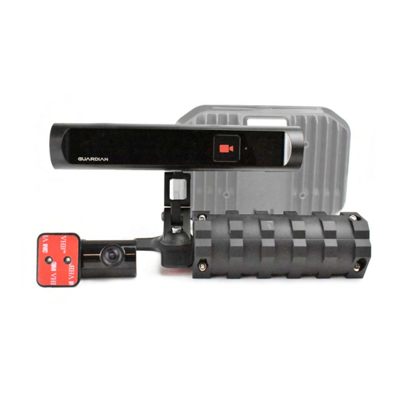
- Page 18 Guardian Field Support Manual 6. STANDARD COMPONENTS ITEM QTY DESCRIPTION IMAGE Controller Unit Hardware: Connection: This is the main processing unit, all components connect to this unit Size: 182x124x43mm Adjustment: Input voltage: 10 to 30V DC (at the Controller) Function: This is the Processor of the system which runs the entire system.
- Page 19 Guardian Field Support Manual Adjustment: Must be squashed flat to be tight, and to be mounted on the opposite side of the Mounting Pan Function: To eliminate loosening from vibration Fastener - Washer: Connection: To fasten Mounting Pan to the...
- Page 20 Adjustment: make sure position is correct before sticking to the dashboard, once down this cannot be reused. Alcohol wipes must be used. Seeing Machines tested the strength using 3M primer. To be covered by SM test standards 3M primer must be used.
- Page 21 Guardian Field Support Manual Alcohol wipe: Connection: For prepping surface before adhesion. Size: N/A Adjustment: After area is cleaned wait 1 minute for evaporation of alcohol. Function: For adhesive mounts to clean off dust or grease (ICS Adhesive mount, FFC mount,...
- Page 22 Guardian Field Support Manual Hose Clamp Hardware: Connection: To the Vibration Motor / Mounting Plate Size: 320mm Hex Head 8mm Adjustment: Tightening up the hex head will give a stronger clamping connection Function: To clamp the vibration motor to the driver’s seat without the use of screws...
- Page 23 Guardian Field Support Manual Adjustment: Clean surface with Alcohol wipes before Function: To affix GPS antenna to the vehicle Power Cable Hardware: Connection: To the Controller Unit and to the In-line Fuse Holders Size: 5m Adjustment: Can be shortened as required...
- Page 24 Guardian Field Support Manual Crimp Terminal: Connection: Connects a cut wire to a threaded bolt or screw Size: Blue Ring 6.3mm Adjustment: Automotive crimps must be used to crimp terminal Function: For power connection Crimp Terminal: Connection: Connects a cut wire to a threaded...
- Page 25 Guardian Field Support Manual 7. INSTALLATION TOOL KIT (Provided by Trainer) TOOL IMAGE Security Torx 20 (T20) Key 24/7 Support Business Card USB Recovery Dongle Information Card USB Recovery Dongle (minimum size 4GB) USB to Ethernet Adapter Software & User Manual for USB to Ethernet Adapter...
- Page 26 Guardian Field Support Manual 8. REQUIRED TOOLS FOR INSTALLATION TOOL IMAGE To adjust locking screw 1.5mm Allen Key on the FFC Installation and Maintenance functions (Windows7, Windows8, Laptop Windows10 or Apple OS are preferred) Laptop must have an ethernet port or a USB...
- Page 27 Guardian Field Support Manual Ratchet spanner set 8, 9, 10, 11, 12, 13, 14, 15, 16, 17, 18, 19mm Vice grips Drill bits 2, 4, 6, 7mm Hole Saws 25mm (1in) Multi-meter and leads Wire cutters/Flush Cutters Wire strippers...
- Page 28 Guardian Field Support Manual Automotive crimpers Torch / Head Torch Scissors Utility Knife (Confirm site requirements) Cordless Drill Cordless Impact Driver Brush Electrical Tape...
- Page 29 FIELD SUPPORT MANUAL Section 2 – Installation of Guardian Generation 2...
-
Page 30: Table Of Contents
Guardian Field Support Manual – Section 2 Table of Contents OVERVIEW ............................4 TECHNICAL COMMUNICATIONS PORTAL (TCP) ................4 LAPTOP & SMART PHONE SETUP ....................7 WINDOWS SETUP ........................7 MAC OS SETUP ........................10 CHROME SETUP ........................13 SMART PHONE SETUP ......................14 3.4.1... - Page 31 Guardian Field Support Manual – Section 2 6.6.1 TROUBLESHOOTING ............Error! Bookmark not defined. 6.6.2 VEHICLE SWAP ..............Error! Bookmark not defined. 6.6.3 BLACKBOX RECOVERY ............Error! Bookmark not defined. 6.6.4 CONFIGURATION CHANGE ON A VEHICLE ....... Error! Bookmark not defined.
-
Page 32: Overview
Controller from left to right due to the design of the connectors. All components of the Guardian Gen 2 system must be mounted and secured in a manner which will prevent the components from becoming a hazard should an incident or accident occur. - Page 33 Guardian Field Support Manual – Section 2 Error Code information; and Online Training Courses. You will access the TCP to complete your online training. Once you are certified you will continue to have access to the TCP (until you are no longer a Certified Technician for SM).
- Page 34 Guardian Field Support Manual – Section 2 When the link has opened select the password and change it to your preferred password (something you easily remember) and click “Reset Password”. We use the information in the TCP to communicate changes and updates to the system to our Installation Certified Technicians.
-
Page 35: Laptop & Smart Phone Setup
These instructions are for computers running the Windows 8 Operating System. These instructions will allow your laptop to communicate with the Guardian Controller Unit via the Ethernet Port. If you do not have an Ethernet Port on your computer, you will need to obtain a USB to Ethernet Adapter (not provided by SM). - Page 36 Guardian Field Support Manual – Section 2 Start typing “View Network Connections” and click on the corresponding words. Right click on “Ethernet” (this can also be called “Local Area Connection”) and click on “Properties”. 1. Scroll down to “Internet Protocol Version 4”...
- Page 37 4. Then click “OK” to save these settings. Note: When the connection is made between the Laptop and Guardian Controller Unit, the Ethernet section will show “Network [#]” where ‘#’ depends on the numbers of networks that have connected to your laptop previously.
-
Page 38: Mac Os Setup
The Controller uses your laptops Ethernet Port to communicate. When you change the settings, the laptop will only communicate with the Guardian Controller. If you use the Ethernet port for other communications, you will need to change this setting back to the original configuration to view your network or Internet. - Page 39 Guardian Field Support Manual – Section 2 Search or find “Network” and double click on 1. Select “Ethernet” in the left-hand panel. 2. Click in the dropdown. Select and click “Manually” to configure the ethernet settings.
- Page 40 255.255.255.0. 3. Click “Apply” to save the settings. Note: When the connection is made between the Laptop and Guardian Processor Unit, the Ethernet section will show Connected. To connect to the Guardian Controller, we recommend using Google Chrome setup on your...
-
Page 41: Chrome Setup
Guardian Field Support Manual – Section 2 3.3 CHROME SETUP Google Chrome Setup If you do not have Google Chrome on your laptop you can download the latest version at www.google.com/chrome and follow the prompts. If you already have Google Chrome, you should ensure that you have the latest version downloaded. -
Page 42: Smart Phone Setup
3.4 SMART PHONE SETUP 3.4.1 PHOTO ARCHIVE It is your responsibility to take photos while conducting Guardian installs. This is to protect you if there are issues with the install, or the client complains of damage to the vehicle after installation. - Page 43 Guardian Field Support Manual – Section 2 An opening setup screen will appear. 1. Make sure “Backup & Sync” is on. 2. Make sure “(free unlimited storage)” is selected. 3. Make sure your Gmail/Google Account is entered, then click “Done”.
-
Page 44: Guardian System Restoration Requirement
This section will describe how to program and use your USB Recovery Dongle for Guardian Gen 2. You will be required to perform a system recovery on every new Guardian install. Note: You will need to be patient the first time you use the USB Recovery Dongle because it takes up to 16 minutes for the dongle to ‘unpack’... - Page 45 Guardian Field Support Manual – Section 2 During the Installation Wizard the software will automatically ‘look’ for the latest version of software provided internet is available and connected. If there is no internet connected, Guardian will continue to search for any software updates, post-installation.
-
Page 46: Preparation For Installation
4 PREPARATION FOR INSTALLATION This chart shows an overview of the steps required to successfully complete an installation Pre-Installation Call Site before arrival Client has Nano SIM Cards • Installation Requirements SIM Cards are activated • Check against the Job Card •... - Page 47 Guardian Field Support Manual – Section 2 During Installation Installation of Hardware Call Support Complete the installation of • If you encounter any errors • the system into the vehicle during the install, as prompted by the IVS Wizard, •...
- Page 48 Guardian Field Support Manual – Section 2 Post Installation Store Photos Paperwork • Archive photos for you to recall if needed • Scan or photograph the paperwork for your records • If you’re using Google Photos (or similar) allow a •...
-
Page 49: Product Installation
5 PRODUCT INSTALLATION The following instructions will allow you to install the Guardian Generation 2. Some general considerations for installs are as follows: You should make sure that you are comfortable with where the cables will run. It is recommended that you conduct a ‘mock’ cable run to ensure that there is enough slack to easily access the Controller. -
Page 50: Component Interconnections
Guardian Field Support Manual – Section 2 5.2 COMPONENT INTERCONNECTIONS REFERENCE DESCRIPTION In-Cab Sensor (ICS) Controller Unit Forward Facing Camera (FFC) 3/4G Antenna GPS Antenna Nano SIM card slot Multi-Function Cable (MFC) – Connects to; Vibration Motor • Cruise Control Disable Cable (CCDC) •... -
Page 51: Installation Records
Guardian Field Support Manual – Section 2 5.3 INSTALLATION RECORDS The installation checklist is to be used to record the installation of a specific Guardian system (by SN) in a specific vehicle. This paperwork is a mandatory requirement for the installation of the system and must be retained for your own records. - Page 52 Client’s fleet. This will allow the Support Centre to preauthorize the list of Guardian serials on Guardian Live prior to the installation to ensure the ability to authenticate with the server during the software install.
-
Page 53: Component Installation Specifics
Guardian Field Support Manual – Section 2 5.4 COMPONENT INSTALLATION SPECIFICS 5.4.1 SIM CARD INSTALLATION SIM Card Installation Important Points to Note: Activated SIM cards must be provided prior to commencing the install. The install cannot continue if you do not have activated SIM cards as the system will not be able to connect to a Network. - Page 54 Guardian Field Support Manual – Section 2 Record the SIM’s serial number on the Installation Checklist (1). Nano size Punch out the SIM (2) SM does not recommend using SIM Cutters to cut the SIM to the correct size. The Nano SIM is to be inserted so that the metal chip is visible (facing up).
-
Page 55: Controller Unit Installation
Guardian Field Support Manual – Section 2 5.4.2 CONTROLLER UNIT INSTALLATION Controller Unit Image The Contoller Unit When installing the Contoller Unit you will need: The Mounting Pan You should use at least 3 mounting screws. It should be orientated so that you... - Page 56 Guardian Field Support Manual – Section 2 Considerations for mounting are: Inside the cabin and away from potential water damage. The processor is rated to IP50 and is not waterproof. It cannot be mounted outside of the cabin. Water damage will void warranty.
- Page 57 Guardian Field Support Manual – Section 2 The Fasteners can be tightened up at both the ‘head’ and ‘foot’ of the bolt. The bolt can also be grabbed in place to hold the Mounting Pan allowing you to organise washers and nuts (see image).
-
Page 58: In-Cab Sensor Module Installation
Guardian Field Support Manual – Section 2 5.4.3 IN-CAB SENSOR MODULE INSTALLATION In-Cab Sensor Module (ICS) Image Mounting Location: The In-Cab Sensor (ICS) houses the driver facing camera and the IR Pods and is to be mounted on the dashboard within -25 to 25 degrees of the driver’s straight-ahead... - Page 59 Guardian Field Support Manual – Section 2 The mounting arm provides the Installer with a degree of flexibility to allow for optimal installation. Installers need to consider the effect that vibration can have on the ICS as a result of the way the mounting arm is secured.
- Page 60 Guardian Field Support Manual – Section 2 Soft Mount: The Soft Mount uses a strong adhesive automotive grade double sided tape. The soft mount can only be used once because the tape is single use. If the soft mount is to be used, the Client is...
- Page 61 Guardian Field Support Manual – Section 2 Adjusting the Mounts: The Sensor Mount has 4 points of movement to allow the flexiblility to achieve optimum sensor placement. The T20 security Torx is to be used for the screws on the Sensor Mount. You can partially lock the sensor in place as finer movements can be made using the ‘locking...
- Page 62 Guardian Field Support Manual – Section 2 The ICS is designed to be mounted at 0° or lower. 0° is considered to be directly in front of the driver’s head. If the ICS has been mounted above the steering wheel (for example) and it has been rotated in a downward direction, it will result in a negative (-ve) value.
-
Page 63: Ffc Installation
Guardian Field Support Manual – Section 2 Adjusting the Yaw The Yaw should be set between -20 to 20 degrees of the drivers head position. Adjust the angle of the ICS (horizontally left and right) so that the sensor is perpendicular to the head position as shown in the image. - Page 64 The FFC “Guardian” logo must be able to be read correctly to ensure the footage is not captured upside down. The Guardian logo should not be upside down.
- Page 65 Guardian Field Support Manual – Section 2 Adjusting the FFC: The 1.5mm Allen key is required to lock the camera in position when the optimal camera view has been achieved. A cap is provided to clip over the lock to prevent tampering.
-
Page 66: 3/4G Antenna Installation
Guardian Field Support Manual – Section 2 5.4.5 3/4G ANTENNA INSTALLATION 3/4G Antenna Mounting Location: The 3/4G antenna must be mounted so that there is a clear line of sight to the sky. The 3/4G antenna can transmit through plastic, wood and fiberglass. -
Page 67: Gps Antenna Installation
Guardian Field Support Manual – Section 2 Make sure you do not have to move the antenna before you affix it. Relocating the antenna after will destroy the adhesive tape and you will not be able to re-attach it. A high gain antenna can be fitted if needed. SM recommends using an FME male to right angle Fakra D key (colour Bordeaux part number Amphenol 3FA1ENDRJ-C04-3) as the patch lead. - Page 68 Guardian Field Support Manual – Section 2 There is a separate adheisive pad allows you to attach the GPS to a surface so that it can be orientated to the sky appropriately. Use caution when applying the adhesive tape to the antenna to avoid removing the Serial Number sticker.
- Page 69 Guardian Field Support Manual – Section 2 There is a magnet located internally on the bottom of the GPS. You may use this to mount the GPS without the need for tape. Note that metal blocks the clear line of site to the sky.
-
Page 70: Vibration Motor Installation
Guardian Field Support Manual – Section 2 5.4.7 VIBRATION MOTOR INSTALLATION Vibration Motor Mounting Location: The Vibration Motor must be mounted on the driver’s seat. It must be located above the adjustment rails and within the red dotted lines as per the image. - Page 71 Guardian Field Support Manual – Section 2 You must mount the Motor to avoid the cable breaking during normal vehicle operation. Therefore, the seat must be able to move freely in all directions. The cabling must be installed with enough slack to allow this movement to occur.
- Page 72 Guardian Field Support Manual – Section 2 The hose clamps must be used to mount the Vibration Motor to an appropriate (strong) bar on the seat. Do not mount the Vibration motor to any flexible bars. You can use the 2 hose clamps in any of the...
- Page 73 Guardian Field Support Manual – Section 2 Use the 2 hose clamps on the outer slots to secure the vibration motor to the mount. Adjusting the Mounts: Using an 8mm socket and your impact driver to tighten the hose clamps (this is the easiest and fastest way to mount).
- Page 74 Guardian Field Support Manual – Section 2 The Vibration Motor cable plug connects to the MFC cable. It does not connect straight to the Controller. To reinforce the strength of the cable connector, it is recommended that you double back the wiring across the connection before securing with the provided zip ties.
- Page 75 Guardian Field Support Manual – Section 2 Note: Where possible, prevent this connection from being in the footwell as it is at risk of being damaged. The end of the cable has a locking mechanism. Ensure you press the locks before...
-
Page 76: Power Cable Installation
Guardian Field Support Manual – Section 2 5.4.8 POWER CABLE INSTALLATION Power Cable Mounting Location: Ensure that you start at the Controller/Mounting Pan (to ensure you have enough length). Route the Power Cable to the fuse box for the power pickup. - Page 77 Guardian Field Support Manual – Section 2 Types of Connection: The system comes with enough crimps to enable you to crimp together the connections. This is the preferred method. Soldering is permitted; however, you must ensure that your soldering joints are protected from shorting out by covering them with electrical tape or heat shrink.
- Page 78 Guardian Field Support Manual – Section 2 To Find a Ground Source (Black Wire): All vehicles have a metal chassis, which is grounded. Most metal bodies around the fuse box are a good ground source; however, you must check the grounding during installation.
- Page 79 Guardian Field Support Manual – Section 2 To Find Ignition (Yellow Wire): Connect the positive (+ve) probe of your multi- meter to your ignition source and the negative (-ve) probe to the ground pickup point you have identified. Switch your multi-meter to measure ‘DC voltage (V)’.
- Page 80 Ensure the vehicle is isolated before performing the power connection The Guardian fuses are to be placed before any other fuses at the fuse box, or as a fuse in the fuse box, if spares are available. This ensures there is no extra load from other 3 party devices which may blow a fuse before Guardian’s fuse.
-
Page 81: Mfc Installtion
Guardian Field Support Manual – Section 2 5.4.9 MFC INSTALLTION Multi-Function Cable (MFC) Mounting Location: The MFC connects the system to: The Vibration Motor. The Cruise Control Disable Cable (Optional Extra See the TCP). Mix Integration Cable Other Fleet Management Systems (FMS) Serial and USB ports. - Page 82 Guardian Field Support Manual – Section 2 The four pin connector plugs into Third Party Fleet Management Systems (FMS) Products (Optional extra) including the Mix Integration Cable. The female micro USB connector plugs into Third Party FMS Products (Optional extra) or any other USB.
-
Page 83: Cabling Installation
Guardian Field Support Manual – Section 2 5.4.10 CABLING INSTALLATION Installation of Cabling Mounting Location: When installing the cabling, ensure you have enough length, with slack, to reach the Controller. Placement of cables: After all components have been installed and the cable routed correctly, the cables... - Page 84 Guardian Field Support Manual – Section 2 There are 2 slots cut into the Controllers case for cable relief. You must push a zip tie into the slot (as shown in the image). You must then secure the cables using the zip tie (as shown).
-
Page 85: Software Setup, Testing & Activation
Guardian Field Support Manual – Section 2 6 SOFTWARE SETUP, TESTING & ACTIVATION The system will not be delivered with default software. If any software is delivered with the system, there is a very good chance that it is not the most recent version of the software. -
Page 86: Applying Latest Software To The Controller
The latest version of the SW will be available via the TCP in the Knowledge Base. Certified Installers can navigate to Guardian Generation 2 > Gen 2 Downloads/Forms where the Recovery Dongle Creator and SW release notes will be found. -
Page 87: Installation Wizard
Guardian Field Support Manual – Section 2 During the re-imaging process the status light on the face of the ICS will flash bright white (with blue tint). When the process has completed the status light will then transition to a... - Page 88 Plug them both together to create your access cable. Plug the Ethernet cable into your Laptop Ethernet Port. Plug the USB adaptor plug into the Guardian Controller. Before starting the IVS Installation Wizard ensure: All peripherals are plugged in to the controller.
- Page 89 Guardian Field Support Manual – Section 2 Note: If the connection fails, check the icon in your System Tray (in the bottom right) and wait until the ‘Unidentified Network’ symbol appears. This will mean that the Controller is ready to connect.
- Page 90 Guardian Field Support Manual – Section 2 Tick the Health and Safety Agreement, which confirms that you have conducted a Health and Safety Check prior to commencing the installation. You will not be able to continue until you have accepted this agreement.
- Page 91 Guardian Field Support Manual – Section 2 Click ‘Continue’. Step 3 – Network Connection This step allows you to enter the information for the SIM card to allow the processor to communicate with a cellular Network. The system will automatically Detect the SIM card (1) and will present a green tick when it is successful.
- Page 92 Guardian Field Support Manual – Section 2 settings or call 24/7 Support. Use the Information button when talking to the Support Technician. Note: The bars represent the signal strength of the SIM card. The bars represent the following: 1. Red, one signal bar – 0 to 10% 2.
- Page 93 Guardian Field Support Manual – Section 2 Step 5 – Time This step verifies that the GPS, System, or Network time is correct. The time will always be presented in UTC. There are articles on the Knowledge Base to help you work out the correct UTC.
- Page 94 Guardian Field Support Manual – Section 2 “Save Configuration” and select ‘System Reboot’. The system will take approx. 2 minutes to reboot. Once the reboot has completed, proceed to the next step. If a Mix Integration cable is not installed, move directly to the next step.
- Page 95 Guardian Field Support Manual – Section 2 Rotation Example (90°): Once set using the slider (if necessary), select “Save Rotation” and select ‘System Reboot’. The system will take approx. 2 minutes to reboot. You will notice the ICS video feed is longer once the reboot is complete and the page refreshes.
- Page 96 Guardian Field Support Manual – Section 2 7.2 Camera ICS Angle (Pitch and Yaw) There are two ways to set the camera: 1. Using the Auto Calibration function (preferred). 2. Using the sliders for Pitch and Yaw (can be used if the Auto Calibration is not functioning properly).
- Page 97 Use the ‘Repeat’ button to conduct the test again if needed. Once you have created your test events for each event type, select “Next”. These test events will be uploaded to Guardian Live as part of the installation validation process.
- Page 98 Guardian Field Support Manual – Section 2 Create Distraction: Step 8 – Authentication Status This step verifies that the system is Authenticated on the AWS server. The system will work through these steps automatically. When all boxes are green, and ticks appear you can proceed to the next step.
- Page 99 Guardian Field Support Manual – Section 2 Step 9 – Review This step confirms that all previous steps are complete and will indicate if an error has been detected (yellow or red symbols). If you see red X’s against any steps, you will...
- Page 100 Guardian Field Support Manual – Section 2...
-
Page 101: System Checks
Guardian Field Support Manual – Section 2 6.3 SYSTEM CHECKS System Checks After the Installation Wizard been completed, you need to complete some system checks to ensure the system is running optimally. Users are required to navigate to the Dashboard page in order to complete these System... - Page 102 Guardian Field Support Manual – Section 2 Tracking Tests: In the ICS Diagnostics tab, make final adjustments to the ICS to ensure that tracking is maintained in multiple seating positions (high, low, close, further away etc). Forward Facing Camera Position: In the ICS Diagnostics tab, observe the FFC video feed.
- Page 103 Guardian Field Support Manual – Section 2 The vehicle can be turned off...
- Page 104 Guardian Field Support Manual – Section 2 To remove your USB to Ethernet adaptor you will need to lift the release pin on the Controllers USB port, and pull out the USB to Ethernet Adaptor. Take care when removing the adaptor.
- Page 105 Guardian Field Support Manual – Section 2 Then pull out the USB port Note: Any USB port with the 2 square holes shown in this image will lock into the Controller USB devices without these holes won’t latch. This concludes the software setup.
-
Page 106: 24/7 Support Details
6.5 ALLOCATING A VEHICLE Vehicle Allocation Calling 24/7 Support with your filled in Checklist will activate a vehicle in Guardian Live and will allow the Client or Distributor to be able to review events in their fleet(s). • Your name (First and Last). - Page 107 Guardian Field Support Manual – Section 2 Any optional extras installed Y/N. The support team will give you a status of what they see over the network to make sure it is running correctly. Then an email will be sent to you confirming the installation.
- Page 108 Guardian Field Support Manual – Section 2 7 FINALISING THE INSTALLATION Finalising the Installation Note: These activities should be completed before leaving the vehicle, but after completing the rest of the install. Tuck all the cables in to the relief and slide...
- Page 109 Guardian Field Support Manual – Section 2 Screw the T20 bolts to lock the Controller Cover onto the Controller. Place the controller in the Mounting Pan and screw the T20 Mounting Pan screws tight. Be respectful to the vehicle owner/driver and leave the vehicle the way you found it.
- Page 110 Guardian Field Support Manual – Section 2 7.1 FINAL QA Final QA At the end of the installation a final Quality Assurance (QA) check is required to be conducted. You must check the following: 1. All components of the system have been installed.
Need help?
Do you have a question about the Guardian and is the answer not in the manual?
Questions and answers
Does this system need to be calibrated to ensure accuracy. If so how often? Thanks.
The Seeing Machines Guardian system has an Auto Calibration function for setting the camera, which is the preferred method. Alternatively, manual adjustments using sliders for Pitch and Yaw can be used if necessary. The information provided does not specify how often calibration should be performed.
This answer is automatically generated