
Summary of Contents for Elite iGATE G500 Series
- Page 1 ADVANCED AVIATION TRAINING DEVICE OPERATOR’S HANDBOOK Model G500 Series Copyright 1989 - 2018 by ELITE Simulation Solutions,...
-
Page 2: Table Of Contents
STARTING UP / SHUTTING DOWN THE IGATE CONTROLS CALIBRATION SCREEN SHUTTING DOWN THE IGATE INITIAL ONFIGURATION NAVIGATION DATABASES ADJUSTING CONTROL SENSITIVITY INSTRUCTOR / OPERATOR STATION (IOS) ELITE MENU STRUCTURE MALFUNCTIONS PAGE OVERVIEW METEO (WEATHER) PAGE OVERVIEW METAR PAGE DATA MODIFICATION PAGE MAP PAGE OVERVIEW CONTROL PAGE... - Page 3 NAVIGATION DATA PAGES METEO (WEATHER) OPERATIONS MALFUNCTIONS PAGE CONTROL PAGE CONFIGURATION PAGE NAV DATA “MODIFICATION PAGE” EXTERNAL VISUAL DISPLAY - GENVIEW™ ONLY 138 GENERAL INSTRUMENTS IPAD CONFIGURATION PAGE CONNECTING FOREFLIGHT® TO ELITE EFS 40 OVERVIEW SHORTCUT CHECKLIST IGATE CONFIGURATION MATRIX...
-
Page 4: Preface
FAA approval for logging flight time credit. Only ELITE ATD software may be used with this training device for certification purposes. The instructions and limitations detailed in the FAA letter of... -
Page 5: General Description
GENERAL DESCRIPTION The ELITE iGATE is one of the most highly advanced IFR flight training devices available today with the best “bene- fit-to-cost” ratio in its class. It is authorized for use in satisfy- ing Tasks/Maneuvers, and Procedures under sections of Title 14 Code of Federal Regulations parts 61 and 141. - Page 6 iGATE aircraft are “generic in-category” aircraft or aero mod- els with correct performance parameters and systems to practice simulated flight, tasks and procedures under IMC or instrument meteorological conditions. Data modeling and per- formance characteristics, however, closely represent actual aircraft specifications and performance of several general avi- ation aircraft.
- Page 7 Under copyright laws, this manual may not be copied, reproduced or dis- tributed in any form or by any means, in whole or in part, without the written consent of the author: ELITE Simulation Solutions AG. Your rights to the software are governed by the accompanying software license agreement.
-
Page 8: License Agreement
A license agreement is a legal agreement between you, the end user (You), and ELITE Simulations Solutions AG “Licensor.” Please read this software license agreement “Agreement” carefully. If you do not agree with the terms and conditions of this Agreement, you should contact ELITE Sim- ulation Solutions AG within 30 days from the invoice date. - Page 9 SOFTWARE OWNERSHIP 1. The enclosed ELITE iGATE software program “Software” and the accompanying written materials are owned by ELITE Simulation Solutions AG, Switzerland, and are protected by United States copyright laws, by laws of other nations, and by international treaties.
- Page 10 Term and Termination 7. This license terminates if you fail to comply with any provision of this Agreement. You agree upon termination to destroy all copies of the program, modifications and merged portions in any form. The original software must remain with the iGATE training device.
- Page 11 14. If You have any questions concerning this Agreement or wish to contact Licensors for any reason, please email info@ flyelite.com or write to: ELITE Simulation Solutions AG Im Schoerli 1 8600 Duebendorf, Switzerland ELITE Simulation Solutions...
- Page 12 iGATE General Description Dual control iGATE, Baron 58 Configuration with AHRS and GNS 430W GENERAL DEVICE DESCRIPTION The power of iGATE trainers is in its versatility and easy conver- sions to support a myriad of aircraft types, classes and avionics systems.
- Page 13 The ELITE iGATE training devices come in closed or open cock- pit configurations. Closed cockpits are made from glossy gel-coat fiberglass with windows that fully enclose the pilots. Open cockpits can be table mounted or mounted to a custom platform depend- ing on space available or customer preference.
- Page 14 DB-style connectors. After the iGATE aircraft hardware has been changed, the last step is to select the corresponding air- craft on startup. The process is simple and quick. ELITE uses a CanBus system as the brains behind the iGATE . Dedicated USB smart cards control each aspect of the training device.
- Page 15 Other than reseating a card or unplugging and replugging a card’s USB cord, no other troubleshooting steps are recommended without the assistance and guidance of an ELITE qualified technician. ELITE USB CanBus System...
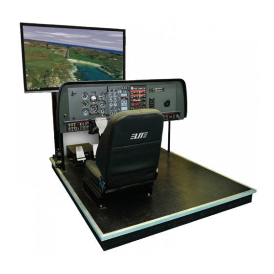
- Page 16 Single Seat iGATE Open Cockpit Configuration with one External Visual Dual Control iGATE with Optional Instructor’s Cabin and Projection Visual...
- Page 17 Single Seat Twin Piston iGATE Closed Cockpit Configuration iGATE Dual Control with Center Console...
-
Page 18: Site Specifications
SITE SPECIFICATIONS ELECTRICAL Power Requirement: 115 - 240 VAC; 50/60 Hz Input Current: 2 x 20A circuits (minimum) Power Consumption: Max 9000 W NOTE: A US electrical grounding plug is provided. Outside of USA, an adapter plug and/or power transformer(s) may be required. - Page 19 Exact room requirements, building access, plans and additional costs must be discussed in advance or prior to any move or relocation. Contact an ELITE representative for additional details.
- Page 20 iGATE with 3 screen projection display iGATE with Curved Screen Projection...
- Page 21 Desktop iGATE Twin Engine w/ G1000 Avionics Cockpit iGATE Twin Engine w/ HSI and RMI...
-
Page 22: Feature Overview
FEATURE OVERVIEW NAVIGATION DATA • US navigational databases (optional world data) • US GenView ™ Visual Database (ELITE visual) • Lockheed Martin P3D Visual Database (optional) • International and local GPS database (optional updates) • Add, delete, and modify navigation facilities/ database elements AVIONICS, INSTRUMENTATION, AND HARDWARE •... - Page 23 MALFUNCTIONS • Fully programmable instrument, power plant, avionics, gear, and system failures • Set immediate, timed, gradual, and random failures • Accurately modeled insidious failure behavior • Virtual instrument covers (for partial panel work) • Create and save an unlimited number of malfunction “state files”.
-
Page 24: Hardwareconnectivity
LAN cable and has (video cable(s) to the main LCD display(s). NOTE: When the HOST computer is connected to the Internet, ELITE technicians have the ability to perform a remote log-in and conduct software upgrades, make adjustments and diagnose issues. - Page 25 The ELITE or P3D visual scenery can be shown on any device that will receive a computer signal (i.e. TVs, monitors, projec- tors). The HOST and VISUAL computers are custom built and configured for the iGATE. Multiple displays may be used to achieve up to 220 degree fields of view.
-
Page 26: Starting Up / Shutting Down The Igate
IGATE STARTUP AND SHUTDOWN NOTE: UPSs (Uninterrupted Power Supplies) are essen- tial to the protection of your iGATE’s electrical equipment! The UPS provides battery backup protection in the event of a power failure and allows an orderly shutdown of equip- ment. - Page 27 IGATE MASTER CONTROL MODULE After power is applied to the iGATE, the above ELITE Master Con- trol Module will appear on the Instructor Operator Station (IOS) monitor after computer boot up is complete. A. Button to LAUNCH all software. B. Reboot all computers or SHUT DOWN all computers.
- Page 28 PRE STARTUP NOTICE 1. Make sure there is no one in the cockpit! 2. For iGATESs with Control Load (CL) flight controls, check that the Emergence Stop is in Neutral position (yellow ring between the red knob and Emergency Stop decal visible)! Emergency Stop Switch Center Console Emergency Stop and Freeze Button Location NOTE: In the event that the CL flight controls move erradical-...
- Page 29 MAIN computer and re- starting it. STARTING THE iGATE 1. Press the LAUNCH ELITE icon on the IOS Master Control Module. Control Loaded flight controls (pitch, roll and/or yaw) will mo- tor throught the full range of operation and return to its neutral position.
- Page 30 3. Choose your navigation database by highlighting your desired navigation area and clicking “choose” or double clicking on the navigation area icon. The main computer will connect or com- municate with the image generator and you will see the aircraft position itself…...
-
Page 31: Controls Calibration Screen
ALL GREEN indicates that components are functioning proper- ly. Failures are indicated with red. A red-lettered component will not allow the pro- gram to continue. Press QUIT then REBOOT ALL at the IOS Master Control Module. problem remains, contact ELITE technical personnel. - Page 32 The second notification is a reminder that simply states that if the training session is used for instrument experience or currency, the weather in the visual scenery must be set to IMC until reaching Decision Height, Decision Altitude or Minimum Descent Altitude. The flight controls, switches, levers and knobs perform the same function as their counterpart in the real aircraft.
-
Page 33: Shutting Down The Igate
Proper shutdown of the iGATE computer systems must be done from the Instructor/Operator Station (IOS) screen. 1. Quit the ELITE program (ALT Q shortcut or QUIT on menu dialog box) to the desktop. 2. At the SCADA Client dialog box, click SHUTDOWN ALL 3. -
Page 34: Initial Onfiguration
You get to the CONFIGURATION PAGE by right mouse clicking on the instructor’s monitor when ELITE is running. This brings up the ELITE Main Menu. Click on CONFIGURATION PAGE or use the keyboard shortcut “alt G”. - Page 35 CONFIGURATION PAGE DESCRIPTION The CONFIGURATION Page is used to: • set ELITE start up preferences • adjust control sensitivity (spring mechanisms only) • change units of measurement for fuel and weight • turn sounds on/off; adjust volume levels • calibrate flight control devices (NOT FOR CONTROL LOAD) •...
-
Page 36: Navigation Databases
NAVIGATION DATABASES When “Ask for Navigation Databases at program start” button is ON, ELITE will ask (on every startup) to select a NAV database area to fly in. “Easy open of Navigation databases” allows you to choose a NAV area by viewing thumbnail maps of all available individual navigation areas installed. - Page 37 Calibration is necessary to bring the iGATE flight controls (yoke, pedal and throttle system) controls (NON CL!) into proper toleranc- es and allow ELITE to learn the limits of the of the controls. (Pressing the HELP button in the Calibration dialog box will open on screen instructions and walk you through the calibration process.) NOTE:...
- Page 38 NULL ZONE (NON CONTROL LOADED ONLY) The center Null Zone panel allows the user to define a “box” with- in which the non CL control device(s) is considered centered. If a flight control does not physically return exactly to center but is still within the limits of the “box”...
- Page 39 Calibration is now complete! Click OK to save these settings & re- turn to the Configuration page, or CANCEL to return and revert to previous settings without saving. Quit and restart ELITE for new calibration settings to take effect. Piper-style SEL Complex & MEL replaceable throttle quadrants (top) Vernier-style SEL Complex &...
-
Page 40: Adjusting Control Sensitivity
USB BUTTON Press “USB” button to see ELITE USB hardware connected ADJUSTING CONTROL SENSI- TIVITY: NON CL FLIGHT CONTROL ONLY! Increase or decrease numbers in the P, R, Y boxes to adjust control sensitivity. Start with low to mid-range. Yaw usually re- quires more dampening than pitch or roll. - Page 41 The selected option will be indicated, replacing the previous selection. NOTE: Some options may NOT be available even though there is a configuration option! Contact ELITE if there are any doubts. NOTE: DO NOT MAKE CHANGES TO INSTRUMENT CONFIG-...
-
Page 42: Instructor / Operator Station (Ios)
INSTRUCTOR / OPERATOR STATION (IOS) MENU DESCRIPTION AND OVERVIEW When the instruments are displayed in the cockpit and the external visual displays shows a runway, the IOS LCD monitor will depict a map screen. From here, the operator can access all areas of the program through a MENU system. -
Page 43: Elite Menu Structure
ELITE MENU STRUCTURE The following is only an overview of the MENU layout. For detailed capabilities and operations, see Program Features. NOTE: Keyboard shortcuts are shown to the right of menu title (for example, ALT Q on the keyboard will exit the program). -
Page 44: Malfunctions Page Overview
MALFUNCTIONS PAGE The MALFUNCTIONS Page is used to initiate failures or create fail- ure scenarios. You have the opportunity to selectively or randomly fail individual instruments, systems, avionics, engines, gear, hydrau- lics and more. NOTE: Malfunction choices are aircraft specific and will vary according to the aircraft class and type. -
Page 45: Meteo (Weather) Page Overview
METEO (WEATHER) PAGE The METEO (meteorological) Page is used to create the weather en- vironment. Various parameters such as visibility, ceiling, wind, turbu- lence, icing, pressure and temperature can be adjusted as desired. -
Page 46: Metar Page
Lockheed Martin P3D visual scenery. The METAR Page is used to download real-time weather reports from METAR reporting stations for use in ELITE GenView. When METAR weather is “engaged” (activated) to function in ELITE, the weather dynamically changes when flying between METAR report-... - Page 47 MODIFICATION PAGE The MODIFICATION Page is used to add, delete or modify up to fifty navaid or facility modifications or additions for each navigation data base area. For example, the US is divided into 9 areas. x 50 = 540 modifications to the navigation database. NOTE: Modifications to navigation data will not be reflected in the GenView visual scenery.
-
Page 48: Map Page Overview
MAP PAGE The MAP Page is a graphical representation of the flying area show- ing navigation facilities, frequencies, lat/long, runways, boundaries and much more. An aircraft symbol shows the flight path in real time (both horizontal and vertical profile views) that can be replayed, saved and printed for evaluation. -
Page 49: Control Page
CONTROL PAGE The CONTROL Page allows you to set date and time of day, airport lighting features and runway markings. Activate yaw control (for us- ing rudder pedals), adjust fuel loading and aircraft weight configura- tion and call sign. Save and load training situations you created (train- ing states) or load optional Instrument Approach Scenarios (IAS). -
Page 50: Instrument Page
(i.e. power settings, frequency changes, OBS selections, etc.) can still be changed and the Hobbs meter continues to run. When first tering ELITE, the program is in the FREEZE mode as indicated by a red MENU triangle in the lower right corner of the screen. When FREEZE mode is released, the aircraft engine(s) will be in the state defined by the aircraft switches and throttles. -
Page 51: Program Features
Simply click on the item to display related help tips. The MAP page is ELITE’s command center. Its use is primarily to setup the aircraft’s initial position for a given flight or procedure, monitor the flight path and to review the flight once you have fin- ished flying. - Page 52 localizers, glide slopes, Flight Information Region (FIR) boundaries, country borders, comments and communication frequencies are all graphically and/or textually represented. Pressing the Profile button brings up a profile view (similar to the profile view on an approach plate). Other knobs, buttons, and data windows located around the periphery of the main map display are used to control the following items, discussed in detail later in this section.
- Page 53 MAP SCALE The actual scale of the Map is indicated on the top right of the screen. The scale appears in green. The scale indication changes according the actual MAP view level, which can be changed with the ZOOM function. NAV DATA SYMBOLS The following Nav Data Symbols are visible on the Map page.
- Page 54 Mouse cursor Localizer transmitter (yellow) ZOOM in Glideslope transmitter (red) Runway with displacement ZOOM out Airport symbol ZOOM Limit (enlarging or reducing) Communication frequencies Head/Distance (Shift key) Add point (route planner) Rroute planner (add or remove waypoint) Change/Move point (route planner) Active runway NOTE: Click on this box...
-
Page 55: Map Information
MAP INFORMATION All elements displayed on the MAP page contain information appli- cable to that specific element such as variation, frequency, runway length, width, lighting, etc. To access information regarding a specif- ic MAP element, click and hold on it with the mouse. For runway information, click on the runway’s threshold. -
Page 56: Reposition Aircraft
REPOSITION To easily reposition the aircraft to a specific ai port and run way, click on the REPOS button located toward the bottom-right of the MAP page. A list of every airport in all currently loaded NAV data- bases will be listed alphabetically by ICAO airport location identifier (LOCID). - Page 57 (or at any time in the future) simply click on TO DEFAULT. With a default airport/runway now saved, ELITE will automatically position the aircraft there on each subsequent startup (assuming the same NAV database/NAVset used to select the default airport/ runway is utilized).
-
Page 58: Multiple Ils Conflicts
XYZ airport, tune the ILS and do not hear identifiers, this is due to the ELITE software not knowing which ILS on which end of the runway you want to use. Therefore you must... - Page 59 To Deactivate the ILS 1. Select <ALT> and <J> simultaneously. 2. The “finger” pointer will change to the “select/ deselect” icon. 3. Using your mouse place the “x” over the apex of the ILS you wish to deselect and push the left mouse button. The ILS anten- na icon will change color from blue to amber.
- Page 60 To Reactivate the ILS 1. Select <ALT> and <J> simultaneously. 2. The “finger” pointer will change to the “select/ deselect” icon 3. Using your mouse place the “x” over the apex of the ILS you wish to reactivate and push the left mouse button. The ILS antenna icon will change color from amber back to blue.
- Page 61 AIRCRAFT SNAPPING Bring the aircraft symbol near any runway thresh old to “snap” to it. This will instantly place the aircraft on the runway threshold (at field elevation) of the runway “snapped” to. This is especially useful for quick repositioning from any location, altitude, heading, air speed etc., to any specific airport runway.
- Page 62 CENTERING Click AC symbol to bring aircraft to MAP center CTRL Click to locate aircraft Conversely, it is possible to move the aircraft to where you have scrolled. Hold down the CTRL (control) key on the keyboard and click the red aircraft symbol or just use the key combina- tion (CTRL-C) by itself.
- Page 63 Level in addition to the preset ZOOM Levels (1, 5, 25, 50, 100, 250, 800, 1250). To store a custom ZOOM Level: • Select the area you would like to ZOOM on by holding down the ALT key and drawing a marquee around the desired area. •...
- Page 64 NOTE: You may de- termine which MAP elements (facilities) are displayed for corresponding ZOOM levels. Click on the appropriate buttons to activate or deactivate the infor- mation to be shown in each ZOOM level. Yellow buttons indicate an active button. •...
- Page 65 In addition to the standard MAP elements (NAV facilities, air ports, land borders, etc.) ELITE has the ability to display an information data block (transponder tag) that moves with the aircraft symbol. This tag is similar in appearance and function to one that might be found on an ATC radar scope.
-
Page 66: Navigation Data Pages
Please note that the reported pressure is the actual ambient pres- sure (not altimeter setting) at the aircraft’s current altitude. Wind speed and direction are displayed graphically using a barb and flag system (see figure on page 105) connected to a “pole” that points in the direction FROM which the wind is blowing relative to True North. - Page 67 There can be several sources of navigation data with the trainer: the data shown on the map screen (provided by ELITE); the GPS nav data provided by Jepp/Garmin and the visual data provided by ELITE, Lockheed Martin or other 3rd party visual provider. All data...
- Page 68 arrow symbol once again and notice that Load Database is now grayed out and no longer avail- able for selection but you can choose to release it (to free memory) or unlock it for modification (to be covered later). NOTE: Multiple NAV databases (regions) can be loaded simulta- neously as desired.
- Page 69 CREATING NAV SETS Following the Open Navigation Databases window, another smaller pop-up window will appear giving you the option to choose either add or replace. To Add the selected database to those already loaded, click on ADD. To replace a currently load ed database with the se- lected one, click on REPLACE.
- Page 70 Champaign-Urbana, Illinois). The approach plate for this demo scenario can be found in the supplements section at the back of this manual or in the ELITE “Manuals” folder on your computer. To load an Instrument Approach Scenario simply click on the “IN- STR APPR SCENARIOS”...
- Page 71 If necessary, open the appropriate IAS folder (EC3, SE3, etc.) for the region you would like to fly in. Select and open the desired Instru- ment Approach Scenario from those listed. NOTE: A description of each scenario can be viewed (before it is opened) by highlight- ing any scenario file name with a SINGLE MOUSE CLICK.
- Page 72 CTRL-R Press CTRL-R to repeat the last ATC transmission directed at your aircraft. Your aircraft identification throughout the scenarios will al- ways be N054EG. Listen carefully for this call sign and follow ATC’s instructions to properly execute the approach. CTRL-K Press CTRL-K to acknowledge and/or answer a request from the program.
- Page 73 STATE PANEL The state panel makes it possible to save and load aircraft “state” files. You can think of state les as a way to take a “snapshot” of the aircraft’s state at any given moment in time. When you save a state le the aircraft’s position, altitude, heading, air- speed, etc.
- Page 74 HEADING PANEL Click in window for reciprocal heading Aircraft Heading can easily be changed with the MAG HDG panel. Magnetic heading in degrees is displayed in the window next to the heading ad just knob. To change it, click and drag on the heading adjust knob until the desired value is indicated.
- Page 75 AIRSPEED PANEL Aircraft Airspeed can easily be changed with the IAS panel. Indicat- ed airspeed in knots is displayed in the window next to the airspeed adjust knob. To change it, click and drag on the airspeed adjust knob until the desired value is indicated. Airspeed changes usually require some re-trimming of the aircraft upon switching back to the instrument panel.
- Page 76 The MAP profile view provides several options for varying display presentation. These options let you tailor the appearance of the pro- file display allowing for improved flight analysis. The four buttons located at the bottom-right of the MAP profile display control these options.
- Page 77 created flying the ILS RWY 7 approach into Orlando Executive (ORL) airport. For illustration purposes, the glide slope was tracked to the non-precision Minimum Descent Altitude (MDA) and NOT to Decision...
- Page 79 Clicking the EXTENDED button when the MAP PROFILE is dis- played expands the profile view to include air speed plot as well as gear and apposition graphs. The EXTENDED but ton functions as a toggle switch turning the expanded display ON/OFF. You can also click the EXTENDED button first (instead of the PROFILE button) to display all four (altitude, air speed, gear, &...
- Page 80 While viewing the MAP profile, even more detailed aircraft informa- tion is accessible for any position along the plotted flight path. First verify ELITE is in the FREEZE mode and the replay function is not activated. Click and hold the mouse button inside the profile area to display detailed information for any position along the plotted flight path.
- Page 81 Now click the RADIAL button then click on any FIX or NAV aid in view on the MAP. ELITE instantly draws a com- pass rose around the selected FIX or NAV aid. Notice at the...
- Page 82 Media-style buttons control play back of the Virtual Flight Data Re- corder (VFDR). REPLAY As you fly, ELITE continuously records your progress with an in- tegrated virtual flight data recorder (VFDR). All recorded flight parameters are accessed via the MAP page. Flight path and profile, gear/flap position, air speed, altitude and heading are all shown and available during the course of your flight.
- Page 83 FAST-FORWARD BUTTON CLICK-AND-HOLD to move FORWARD through recorded flight path. DOUBLE-CLICK to jump to END of recorded flight path. SLOW BUTTON CLICK to SLOW replay speed. STOP BUTTON CLICK to STOP Replay. NOTE: The “ACFT Information” box is not available during flight path replay.
- Page 84 INSTRUMENTS REPLICATED ON MAP PAGE The first time the REPLAY feature is used an “Initial settings for Re- play functions” dialog box will appear. This box specifically relates to, and is used to define, how the instruments will be displayed on the MAP page.
- Page 85 PATH BUTTON Flight path and associated data recorded by ELITE’s VFDR can also be saved in a path file. The number of path files stored is limited only by available disk space. These stored path files can be loaded at any time in the future and then displayed and/or replayed on the MAP page for analysis.
- Page 86 CLEAR BUTTON The CLEAR button clears the flight path from the MAP page and deletes all associated flight path data from memory. ROUTE BUTTON Similar to the flight path files discussed in the preceding section, you may also save a self-created route into a Route file by using the ROUTE button.
- Page 87 HEADING / DISTANCE CURSOR E6B-style calculations can be displayed using the TIME / SPEED / DISTANCE feature. To display magnetic track, heading, distance and time from the red aircraft symbol, to any point in the selected NAV database: Hold down the SHIFT key on the keyboard. The TIME / SPEED / DISTANCE cursor appears Click and hold anywhere on the Map page.
- Page 88 Time (ETA) shown is calculated from the aircraft position to the se- lected point based on groundspeed. NOTE: Change wind settings on the METEO page to see the effects of different winds on ETA, heading, and ground speed. You can also observe the effects of differing aircraft speed and/or altitude in a similar manner.
- Page 89 MOVE POINT Push the CTRL & SHIFT keys on the key board and the cursor changes to “move point. ” Click on any route point you want to move and drag it with the mouse to another location. Release the mouse button and changes take effect.
- Page 90 Press ALT-A to engage or disengage mode. Once engaged, enables you to manually select ELITE’s “active” runway by clicking on the threshold of desired runway (runway color changes to green to iden- tify that it is active). You can change your selection as many times as you like while the manual selection mode is engaged.
- Page 91 3. Change runway selection as desired 4. Deselect by clicking anywhere off the selected runway 5. ALT-A to disengage manual selection mode AIRPORT FREQUENCY INFORMATION COMM (communication) & NAV (navigation) frequencies for asso- ciated airports and NAV facilities are in the database. As described earlier in the chapter, the MAP page also functions as a virtual A/FD (airport/facility directory).
- Page 92 ACC - Area Control Center ACP - Airlift Command Post APP - Approach Control AWO - Automatic Weather Observing Station (AWOS) CLD - Clearance Delivery CPT - Clearance Pre-Taxi CTL - Control DEP - Departure Control DIR - Director (Approach Control/Radar) EMR - Emergency FSS - Flight Service Station GND - Ground Control...
-
Page 93: Meteo (Weather) Operations
METEO (WEATHER) PAGE The METEO (meteorological) page is used to create the weather environment in ELITE. Parameters such as visibility, ceiling, wind, turbulence, pressure and temperature can be set and changed as de- sired to tailor the weather to meet your specific training need. - Page 94 We will examine each of these elements in greater detail in upcoming sections. METEO CLOUD SECTION METEO WIND SECTION...
- Page 95 DYNAMIC WEATHER In addition to setting static (unchanging) weather conditions, the METEO page also allows you to create dynamic (changing) weather conditions. Dynamic weather is set up by first specifying a time peri- od with in which these changes will occur by dialing in values (min- utes) in each of the windows under the corresponding “Between”...
- Page 96 In addition, this column can be referenced when Active METAR data is engaged, as it will reflect weather changes over time and lo- cation. As both dynamic and static weather are reflected, it is easy to get a quick picture of the weather with just a glance. STATIC WEATHER To set static (unchanging) weather use the “To”...
- Page 97 WIND There are three wind layers in the ELITE weather environment. Each wind layer can have its own characteristics and are all configured in the same way on the METEO page utilizing identical control panels. Wind layers can NOT be less than 200 feet thick. The thickness of each layer is defined by the values entered on the panels.
- Page 98 STANDARD VIEW There are two inherent “transition zones” each 100 feet thick be- tween the top/mid layers and the mid/bottom layers respectively. These transition zones comprise the last 50 feet of each layer (the lowest part of the higher layer and the highest part of the lower lay- er).
- Page 99 WIND SPEED Wind speed in knots (0-60) is set by clicking the UP and DOWN arrow buttons. To make the wind speed variable simply press the +/- button. TURBULENCE Turbulence level 1(light) through 12(extreme) is set by click- ing the UP and DOWN arrow buttons. Separate turbulence levels can be set for each of the three corresponding wind layers.
- Page 100 VISIBILITY Above Cloud Layer 1: Select visibility using UP/DOWN arrows as desired. NOTE: Visibility can only be adjusted if cloud layer 1 coverage is set to OVERCAST. With an OVERCAST layer programmed, selected visibility will be- come the controlling visibility above the TOP of the OVERCAST up to FL400 (40,000ft).
- Page 101 NOTE: CAVOK by definition also indicates (in part) that no clouds or precipitation exist below 5,000ft. Pressing the CAVOK button in ELITE with Cloud Layer 3 Base set to <= (less than or equal to) 5100ft MSL will also set cloud coverage to Sky Clear (SKC) in addi- tion to changing visibility to 30 statute miles.
- Page 102 SKC Sky Clear FEW 1/8 cloud coverage SCT 2/8 to 4/8 cloud cov- erage BKN 5/8 to 7/8 cloud coverage OVC 8/8 cloud coverage Cloud bases can also be defined by pressing the corresponding UP/ DOWN buttons. Tops can only be specified for an overcast (OVC) layer.
- Page 103 ALTIMETER Altimeter setting in hectoPascals (same as millibars) and/ or inches of mercury can be set by clicking the appropriate UP and DOWN arrow buttons. NOTE: By creating a dynamic (changing) pressure over time sce- nario it is easy to demonstrate the “Going from a HIGH to a LOW lookout below”...
- Page 104 The goal of any simulation is to sharpen your “situational” aware- ness. This is not only geographic (positional) awareness but “how are things going” awareness. ELITE’s intent is not to prepare you for how to exactly react to an icing “encounter” (that is best learned from the POH, aircraft manufacturer, &...
- Page 105 Icing can be implemented in two different ways. Press “Enforce” and choose an intensity level (Light, Mod- erate, Severe) to activate icing regardless of OAT or visible moisture present. This can be used by an instructor for example to demon- strate the effects of icing on aircraft performance at any time.
- Page 106 Notice that Pitot tube icing is NOT part of the icing factor equation. Pitot tube icing is actually controlled separately on the MALFUNC- TIONS Page. This separation of control is intentional. Although Pitot tube icing is often coincident with structural icing, structur- al icing can be subtler to reveal itself (initially).
- Page 107 The Ref. Meteo Time RESET button sets the Reference Meteo Time back to zero minutes. This is used in conjunction with the interval settings to control dynamic weather as explained next. REFERENCE METEO TIME The Reference Meteo Time is simply an elapsed time counter that runs as the aircraft is flown.
- Page 108 The Reference Meteo Time can be RESET back to zero at any time in the flight. This will allow dynamic weather scenarios to be easily repeated. One important point to keep in mind is that if you have been flying a given sim session for an extended period of time, then set up some dynamic weather, make sure to either RESET the Ref- erence Meteo Time or set time intervals in the future.
- Page 109 MALFUNCTIONS PAGE “HELP Tips” are available anytime by pressing ALT-H. Move the help cursor (?) over any on-screen item that you would like more information about. When the help cursor reveals its document icon help is available for that item. Simply click on the item to display related help tips.
- Page 110 Although the MALFUNCTIONS Page might appear complex at first glance, similar to the METEO Page it is actually quite easy to use and is one of the most comprehensive available. You have the opportu- nity to selectively or randomly fail individual instruments, systems, avionics, engines, gear, flaps, and much more.
- Page 111 AI - attitude indicator DG - directional gyro VSI - vertical speed indicator ALT - altimeter ASI - airspeed indicator TC - turn coordinator FAILURE TIME WINDOW The “Between” column is used to set the “failure time window” inter- val. The values entered in minutes (00-99) are compared to the Ref. Failure Time and determine when or during what time period (win- dow) the corresponding ARMed failure will occur.
- Page 112 IMMEDIATE FAILURE To invoke an immediate failure, enter the SAME values (minutes) in each window that correspond to the current Ref. (reference) Failure Time displayed at the lower-left. If for example the Ref. Failure Time displayed is 07 (7 minutes), enter 07 in BOTH “Between” windows next to the desired ARMed failure.
- Page 113 INSTRUMENTS AND RECEIVERS Failures in this panel are setup in much the same way as previously dis- cussed except that immediate failures are invoked by using the ARM buttons in the “immediate” column. To set a specific failure time or a failure time window interval you must use the ARM buttons in the “Timed”...
- Page 114 ENGINE FAILURES Failures in this panel are set up exactly the same as the previous (In- strument / Receivers) panel. Note that it is not only possible to fail an engine, but to also simulate a power loss (leaving partial power). Combine this with various “auxiliary”...
- Page 115 12 minutes, then entered 2 in the Instruments window, ELITE would randomly fail two of the six instruments (each at some random time between 3 and 12 minutes). NOTE: “Engines” does NOT refer to the number of engines but rather to the number of possible engine failures.
- Page 116 FAILURE “STATES” Similar to saving and loading METEO States, the SAVE and LOAD buttons next to “Failure State” enable you to Save and Load Failure States. You can literally develop a library of these states that can be instantly recalled for use anytime. Create a failure scenario (state) and tweak it until you are satisfied, then click the SAVE button to open the Save Malfunction files dialog box.
- Page 117 Use the “Clear all failures” button to RESET the entire MALFUNCTIONS page (including failure time intervals). REF FAILURE TIME The Ref. Failure Time RESET button sets the Reference Failure Time back to zero minutes. This is used in conjunction with the fail- ure time window interval set tings as described previously.
- Page 118 Instrument Approach Scenarios, save/ load “STATE” files, and more. VISUAL DATE & TIME PANEL Use the Visual panel to con- figure ELITE’s visual display settings. Everything from Time-of-Day to the amount of runway environment de- tail displayed can be changed.
- Page 119 Set the Time of Day and Date. Daylight is accurately reflected based upon navigation data loaded and time set. At program start, ELITE references your computer’s internal clock, then applies the (LT)/(UTC) offset from the General settings dialog box on the Configuration. The calculated current UTC (Universal Time Coordinated) time is then used for all cockpit clocks and ap- pears on the Time of Day panel in the UTC window.
- Page 120 These buttons control various parameters used to create the view of the outside world and determine the resulting “Level of Detail” implemented by these parameters. “Fast” computers can normally use a HIGH setting, while relatively “slower” computers may re quire a LOW or MEDIUM LOD setting.
- Page 121 ENGINE “ON” AT STARTUP The engine(s) start automatically at initial program startup when the ON button is active. To start engines manually (with checklist) turn off (ON button NOT lit) AIRCRAFT PANEL The heading, altitude, and airspeed panels found on the MAP page are duplicated here for convenient aircraft setup while using the Control page.
- Page 122 STATE PANEL The STATE panel makes it possible to save and load aircraft “ state” files. You can think of state files as a way to take a “snapshot” of the aircraft’s state at any given moment in time. When you save a state file the aircraft’s position, altitude, heading, airspeed, etc.
- Page 123 State files can be saved at any time. Before saving a state file make sure that the aircraft is set up just the way you want it. Once every- thing is to your liking be sure to name the state fi le something that will be meaningful now and in the future.
- Page 124 Highlight the “state” file you wish to load from those listed, then click OPEN. TIME FLOWN PANEL The Time Flown panel always indicates the elapsed time ELITE has been flown. Time automatically stops when the flight is frozen or while not flying on the Instrument panel.
-
Page 125: Configuration Page
Startup procedures in Chapter One. STATE FILES When the “Ask for State File at Program Start” button is ON, ELITE will display a dialog box (on every startup) allowing you to choose any training “State File” previously saved. You will be positioned with the same aircraft in that specific state (including Nav data and Meteo State selected!). - Page 126 07:00, i.e. 12:00UTC - 5Hrs = 07:00. For periods of Day light Saving Time (UTC-4) in Orlando, this value would be set to 08:00. To have ELITE perform this calculation au- tomatically (recommended) simply click the “Take Local Time...
- Page 127 ATD DETECTION REPORT With ATD Detection Report button ON (ATD version only), ELITE will verify (on every startup) connection and proper communication with the required hardware necessary for use as an approved ATD (Aviation Training Device). If a required device(s) is not present or...
- Page 128 MEASUREMENT FOR WEIGHT & FUEL You can choose what units of measurement are displayed for weight and fuel values as desired. • Weight in pounds or kilos • Fuel in liters, U.S. gallons or Imperial gallons CHANGING COLOR OF NUMBERS For readability, you can change the color of numbers shown on all pages (except the instrument panels.) Click on RED or YELLOW as desired.
- Page 129 NOTE: Engine sound can also be switched ON or OFF with the “E” key on the keyboard. 3D SOUND For ELITE technicians only! The iGATE sound will be properly configured before installation. Do not change settings without con- sulting ELITE technical support personnel. Depending on hardware configuration, 3D sound ON allows for an enhanced audio experi- ence on 3D compatible sound systems.
-
Page 131: Nav Data "Modification Page
The Modification Page allows you to create or modify up to 200 facilities, fixes, NAVaids or holding patterns in each navigation data base worldwide. This NAV DATA is inherent to ELITE software only. Only modification of variation will be relfected in the P3D... - Page 132 Click on the MODIFY button and then the desired facility to be changed. A window will appear with the specific data of the facility. Data can be changed and the change will take effect after clicking on the OK button. DELETING FACILITIES Facilities can be deleted as well as created and modified.
- Page 133 UNDO CHANGES To return to the original status of facilities, you can undo modifica- tions or deletions. Hold the ALT key while clicking on the MODIFY button. The following pop-up window will appear on the screen. Now, select and choose to undo changes. To restore an original facility that had been deleted, hold the ALT key while clicking on the DELETE button.
- Page 134 When 200 modifications have been made the following message appears: FACILITY INFORMATION Click and hold the mouse on any facility to display detailed informa- tion about that facility. For run way information, click on the runway threshold. When facilities are in the same location or covered by other ones, click on the same spot once more...
- Page 135 ADDING FACILITIES...
-
Page 138: External Visual Display - Genview™ Only
EXTERNAL VISUAL DISPLAY - GENVIEW™ ONLY GENVIEW VISUAL DISPLAY GenView™ is an add-on visual display database that will allow you to fly in the virtual world with accurate digital elevation models (DEM) and vector data accurately depicting rivers, lakes, highways, railroads and built up areas. - Page 139 NAVaids are always accurate, the layout and orientation of taxi ways may not represent the exact layout at that airfield. 2. When ELITE is first loaded, the default position of the aircraft is on the end of the run way. You can reposition the aircraft relative to the taxiway in three ways: a.
-
Page 140: General Instruments
GENERAL INSTRUMENTS ARTIFICIAL HORIZON AIRSPEED INDICATOR The airspeed indicator (ASI) is indicated in knots on the ASI in- strument. The white, green and yellow arcs as well as the red line have the standard meaning. True airspeed may be calculated by applying the usual techniques assuming ISA temperature. - Page 141 TURN INDICATOR The Turn Indicator (Turn coordinator) is actually a combination of two instru- ments. The aircraft symbol indicates rate of roll and rate of turn and is proportion- al to the roll rate. When the roll rate is The artificial horizon or reduced to zero, the instrument provides attitude indicator is the an indication of the rate-of-turn.
- Page 142 GYRO COMPASS The Gyro Compass (if equipped) indicates the actual heading. It has a turning compass card. The directional gyro (DG) is not slaved with the compass and will precess. As in the actual aircraft, it must be adjusted. The orange arrow (heading bug) can be set with the rotary dial on the avionics console HDG BUG sub panel.
- Page 143 VOR/LOC/GLIDESLOPE INDICATOR The VOR/LOC/Glideslope Indicator utilizes the conventional cross pointer layout. It is connected to the NAV receivers (NAV1 or NAV2). The compass card is rotated by the OBS knob in the conven- tional manner. Receiver is set to a VOR Receiver is set to an ILS The RADIO MAGNETIC INDICATOR (RMI) incorporates a slaved (self -rotating) compass card, a green...
- Page 144 GPS unit), NAV2/COMM2 (KX 165 TSO), ADF (KR27)and a Flight Director/Autopilots (KFC 150). Optional avionics include EFS 40 or E500 (ELITE AHRS). iGATEs are also available with OEM Garmin GNS 430W, GNS 530W, GTN 650, GTN 750 or G1000.
- Page 145 NOTE: When a receiver is tuned to a frequency, the closest NAVaid with this frequency is received. When two facilities in the same area have identical frequencies, ELITE will show a di- alog box to select the desired one. MARKER RECEIVER...
- Page 146 LO selection may be made to set marker reception to low sensitivity, i.e. markers will only receive data at a short distance, such as during the approach. The marker lamp panel consists of the conventional: A lamp (white when lit, airway marker, inner marker), O lamp (blue when lit, outer marker), M lamp (amber when lit, middle marker).
- Page 147 USING THE COURSE/HEADING PANEL NOTE: Instrumentation may vary among trainers The Course/Heading is used to set course and headings using either the HSI/ flight director (if equipped) or using VOR #1 OBS and VOR #2.OBS. In addition, the altimeter setting and radar altimeter bug may also be set as necessary.
-
Page 149: Ipad Configuration Page
Configuration Page The ELITE iGATE ATD has a built-in WiFi network that will allow you to connect your iPAD to the ELITE master computer and sync with certain popular navigation and utility Apps. The iGATE is currently compatible with the following iPAD applications: •... -
Page 150: Connecting Foreflight® To Elite
4. Press “Send” under the Broadcast Foreflight column. 5. Start Foreflight® on your iPad. 6. Press the “more” button”, then go to devices. ELITE will appear as a “device”. 7. Select the ELITE device and enable it. The ELITE device will display as connected. -
Page 151: Efs 40 Overview
ELECTRONIC FLIGHT INSTRUMENTATION SYSTEM EFS 40 PILOT’S GUIDE NOTE: EFS 40 is an optional instrumentation system available for iGATE systems. EFS appropriate masks and control heads are included. EFS Control Module For the purposes of this manual, the intent is not to provide a complete pilot’s guide but to give an introduction to and abbrevi- ate commands associated with the EFS 40. - Page 152 Abbreviate Operation of the EFS Control Panel...
- Page 153 The EFS 40/50 uses a defined color set which aids the pilot in inter- preting displayed information. A brief summary of the color set is as follows: Warnings Cautions/Abnormal Source Yellow Scales and associated figures White On-side approach and navigation data Green Cross-side NAV data Yellow...
- Page 154 EFS Symbol Definition...
- Page 155 EADI Symbology Definition...
-
Page 156: Shortcut Checklist
SHORTCUT CHECKLIST...
Need help?
Do you have a question about the iGATE G500 Series and is the answer not in the manual?
Questions and answers