Table of Contents
Advertisement
Quick Links
Advertisement
Table of Contents

Related Manuals for Hillphoenix CO2One

Summary of Contents for Hillphoenix CO2One
- Page 1 Condensing Unit Manual DECEMBER 2021...
- Page 2 Hillphoenix products as they pertain to this installation. Any information pertaining to products referred to in this manual that are not provided by Hillphoenix is in no way intended to be authoritative or in any way ensured to be accurate.
- Page 3 For a list of Hillphoenix- authorized installation and effective and efficient way possible. For a list of Hillphoenix-authorized installation...
- Page 4 Safety Labels The warning labels shown in the table below are present on the equipment. PLATE DESCRIPTION Indicates that it is forbidden to remove the safety devices and protections installed; it is usually accompanied by the explanatory wording: DO NOT REMOVE THE PROTECTIVE DEVICES.
- Page 5 One Condensing Unit Hillphoenix Refrigeration Systems Position of the Pictograms 1. On all the air exchangers present in the equipment 2. On each surface subject to high temperatures 3. On each energized part...
- Page 6 Hillphoenix cannot be held responsible or liable for damages caused by incorrect use of the documentation. In order to avoid actions that could cause danger to persons, it is important to read and understand all the documentation accompanying the equipment.
- Page 7 There may be occasions however, when a particular item or part is not included when the system or product is shipped. Any claim for missing items must be made to Hillphoenix within 48 hours of receipt of the equipment.
- Page 9 Hillphoenix Refrigeration Systems General Conditions The manufacturer, Hillphoenix, Inc., guarantees the equipment produced by the manufacturer itself as being free from material and processing defects for a period that is agreed upon when the contract for the sale of the same unit is concluded.
-
Page 10: Table Of Contents
Table of Contents Section 1: Overview ..........1 Introduction . -
Page 11: Section 1: Overview
These assembly instructions are an integral part of the CO One product (identified in this document as the equipment or unit) produced by Hillphoenix, Inc.; they will need to be included in the documentation for the equipment when it is installed. -
Page 12: Contents Of The Assembly Instructions
One Condensing Unit Hillphoenix Refrigeration Systems Contents of the Assembly Instructions These instructions are intended for technicians to understand and correctly install the equipment. These instructions also provide guidance for: • Correct transportation and installation of the equipment • Performing correct cleaning, adjustment, and maintenance of the equipment •... -
Page 13: Conventions And Definitions
Conventions and Definitions The assembly instructions for the uninstalled equipment were divided into sections to enable, for each life phase of the equipment (transportation, installation, maintenance, and decommissioning), readily available information necessary for the user of the equipment. The entire documentation relating to the equipment was prepared in accordance with current safety regulations. The configuration of certain elements or devices described or represented in the documents may differ from that of the equipment in the specific setup created according to particular requirements or safety regulations;... - Page 14 One Condensing Unit One Condensing Unit Hillphoenix Refrigeration Systems Hillphoenix Refrigeration Systems Personal Protection Equipment and Rules of Conduct For each of the procedures described in these instructions, mandatory protective measures and safety guidelines are specified for the safety of any personnel operating the equipment.
-
Page 15: Section 2: General Safety Information
Section 2: General Safety Information Engineering Criteria The equipment has been designed in compliance with the standards indicated in the table below. STANDARD NAME Safety of Household and Similar Appliances, Part 1: General Requirements, Edition 6, UL 60335-1 Issue Date 2016-10-31 CAN/CSA-C22.2 No. -
Page 16: Devices And Solutions For Protection
One Condensing Unit Hillphoenix Refrigeration Systems Devices and Solutions for Protection Passive Safety Devices The equipment includes the following safety devices and features: • Fixed guards close to the moving parts • External fairing with fixed access doors (if equipped) •... -
Page 17: Residual Risks
To avoid any dangerous condition for persons or damage to the equipment caused by residual risks, i.e., those risks that persist despite all provisions implemented, or potential risks which were not obvious, Hillphoenix recommends that maintenance personnel and all personnel in charge of operating the equipment strictly follow the warnings indicated on the following pages. -
Page 18: Incorporation Statement
DANGER: The user MUST confirm the type and quantity of gas contained in the equipment to ensure proper operation. ATTENTION: It is essential to consult Hillphoenix prior to any unapproved use. DANGER: All work involving R744 (CO2) refrigerant must be carried out only by qualified technicians trained to work with this type of refrigerant. - Page 19 • Staff responsible for maintenance of the equipment must be aware of all the procedures outlined in Section 5: Maintenance and must have adequate technical training to correctly interpret the instructions and diagrams attached to these instructions and to perform maintenance on the equipment. •...
-
Page 20: Section 3: Description Of The Equipment
One Condensing Unit Hillphoenix Refrigeration Systems Section 3: Description of the Equipment The condensing units described in this document are designed for use in commercial refrigeration. These condensing unit systems are intended for use in locations where heat can be released outside of the building in which they are installed.. - Page 21 The compressors are managed by a dedicated inverter, which allows modulation of the capacity from 25 to 100%. The compressor(s) can be include a bypass solenoid to facilitate starting. Each line includes a check valve. The unit is equipped with pressure switches and safety valves to address any malfunctions. In addition, there are: a high-pressure valve (HPV) in general delivery after the gas cooler, intermediate liquid and gas separation receiver, a flash gas bypass to keep the pressure constant at the receiver itself (only in certain configurations), a braze-weld liquid filter with relative indicator, a liquid-intake heat exchanger (if equipped),...
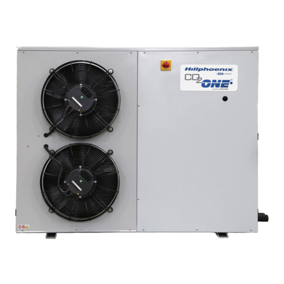
- Page 22 One Condensing Unit Hillphoenix Refrigeration Systems 1. RH compressor compartment door and 3. LH gas cooler compartment door electrical enclosure 4. Gas cooler fans 2. Main switch/disconnect 1. Electrical panel 3. Master power switch rod 2. Display* 4. Compressor compartment...
-
Page 23: Identification Plate
Identification Plate For identification of the unit, a specific UL identification plate has been affixed; the identification data shown on this plate must be reported to the manufacturer’s offices for each request for service or for the ordering of spare parts. - Page 24 One Condensing Unit Hillphoenix Refrigeration Systems Name Series: CO One with motor Size of compressor(s) Type of application: M = medium temperature (MT) L = low temperature (LT) Number of fans: 1 = an electronic fan-motor 2 = two electronic fan-motors...
- Page 25 Technical Data The supporting documentation includes the following detailed technical information on the electric and refrigeration specifications for an individual unit: • R744 (CO2) as the only usable refrigerant • Machine code • Number and model of compressors (including MT/LT compressors) •...
-
Page 26: Section 4: Transport And Installation
One Condensing Unit Hillphoenix Refrigeration Systems Section 4: Transport and Installation DANGER: The procedures outlined below must be carried out by qualified operators. The manufacturer declines all responsibility for activities conducted while not complying with the appropriate safety regulations, work performed by unqualified operators, and any actions not complying with the specifications of this manual. -
Page 27: Transport And Handling
ATTENTION: The power supply to the partly-completed machine may be different from that of the associated evaporator unit. Transport and Handling All requirements must be strictly followed during the transportation and handling of the equipment and during its assembly and installation. ATTENTION: During transport and handling, the operator must use all necessary Personal Protective Equipment (PPE). - Page 28 One Condensing Unit Hillphoenix Refrigeration Systems Lifting for handling and subsequent positioning of the unit must be performed using straps that must be inserted into the appropriate lifting pockets of the structure, as shown in the following figure. Follow these additional recommendations for correct handling.
-
Page 29: Installation
Installation ATTENTION: The equipment that is the subject of this manual is part of a refrigeration system consisting of the condensing unit and components of a refrigeration system such as evaporator(s), pipes, and safety components. The equipment is designed for use outdoors. The total volume of the evaporators associated with the equipment must NOT exceed .3 cubic foot. - Page 30 One Condensing Unit Hillphoenix Refrigeration Systems The equipment must be installed on a horizontal plane to enable carrying out the necessary maintenance safely. The following figure shows the minimum distances regarding the recommended safety distances. Secure the unit to the floor by using the holes on the anti-vibration supports.
- Page 31 The power supply provided by the customer (voltage, phases, and frequency) must be correct and sufficient to adequately power the equipment. Specifically, the following requirements must be met: • If required for a particular equipment configuration, install a differential electromechanical circuit breaker between the power supply line and the door lock switch installed on the equipment.
- Page 32 One Condensing Unit Hillphoenix Refrigeration Systems • Management of the low-temperature system (if equipped) Wiring of the Various System Components The equipment components must be wired properly prior to powering up the system: • Supervision network (if equipped) • Other optional components ATTENTION: The sizing and laying of the cables that connect the equipment to all its external components must be carried out in compliance with local codes and ordinances.
- Page 33 ATTENTION: The pipes must be sized according to the type and extension of the system in full compliance with the safety restrictions imposed by local codes and ordinances. Hillphoenix is not responsible for the incorrect selection and execution of the system pipes.
- Page 34 One Condensing Unit Hillphoenix Refrigeration Systems ATTENTION: To avoid problems with the condensing unit, do not install components or safety valves rated for less than 45 bar on the suction line. ATTENTION: The system components, pressure ratings, and safety criteria must conform to all local codes and ordinances.
- Page 35 The dimensions of the outlet pipes (intake line and liquid line) shown in the refrigeration diagram are calculated for a MAXIMUM TUBING LENGTH of 98.4 feet. This maximum length, valid for each individual section of both intake and liquid, has been defined in order to obtain a pressure drop that does not compromise correct functioning of the evaporator.
- Page 36 If there is no pressure in the circuit, do not install the equipment and instead contact Hillphoenix Technical Support. ATTENTION: Prepare the connections by making a clean cut using appropriate tools.
- Page 37 Low refrigerant pressure Conditions that can cause low suction pressures are: • Insufficient refrigerant charge • Improperly operating metering devices • Refrigerant leaks An improper charge can result in reduced efficiency and can cause compressor failure. If refrigerant loss occurs, safeguards are enabled to prevent operating with insufficient pressure.
- Page 38 One Condensing Unit Hillphoenix Refrigeration Systems Braze-only connections Information on the type of connection possible can be found on the refrigerator diagram. 1. Cut the cap 3. Braze the line 2. Prepare for brazing RS service valve 1. 1. Closure cap Closure cap a.
- Page 39 The oil in the compressor is PAG (polyglycols) 100 made by FUCHS RENISO PAG 100. ATTENTION: Do not charge with any oil other than that specified by the manufacturer. For further information, contact a Hillphoenix service representative. ATTENTION: The pre-charge must be run immediately prior to draining.
- Page 40 Before terminating the evacuation procedure, the circuit must be loaded with 3.5 ounces of oil. The oil in the compressor is PAG (polyglycols) 100 made by FUCHS RENISO PAG 100. ATTENTION: Do not load any oil other than that specified by the manufacturer. For further information, contact a Hillphoenix Field Support Engineer.
- Page 41 Proceed as follows: • Close valve R1. • Close general liquid valve R2. • Also close valve R3 (LT versions only). • Use valve RSS to load oil while applying suction with the vacuum pump to service valve RSD (MT versions) or RS1 (LT versions).
- Page 42 One Condensing Unit Hillphoenix Refrigeration Systems During refrigerant pre-charging, it is necessary to use CO2 gas at a pressure value well above the triple point (5.185 bar(a)) to avoid the formation of dry ice inside the system. Charging gas at 10 bars is recommended throughout the circuit.
- Page 43 ATTENTION: Do not charge any oil other than that specified by the manufacturer. For further information, contact a Hillphoenix service representative. The amount of oil may need to be adjusted in light of the refrigerant load, with reference ot the following table.
-
Page 44: Preparation For Startup
Preparation for Startup DANGER: The following procedures must out be carried only by qualified and specifically trained technicians. Hillphoenix declines all responsibility for activities carried out without respecting the safety regulations, by unqualified operators, and without compliance with the specifications of this manual. - Page 45 Before bringing the equipment to full capacity, a number of preliminary checks are necessary to carriy out at startup. Check valves Make sure that all the valves on the equipment and on the system are open, that the service valves are closed, and that they all are fitted with caps.
- Page 46 One Condensing Unit Hillphoenix Refrigeration Systems Electronic control To start the system, it is necessary to follow this sequence of steps: • Set the disconnector (1) of the electrical panel to ON to supply the entire system. • Set the electronic control to ON via the display (2).
- Page 47 Looking at the display on the door of the electrical panel, the following are evident: BUTTONS ASSOCIATED ALARM List of active alarms and access to the alarm logs PRG. Access the main menu BACK Return to the previous page Switch to the upper value in a list or increase the value of a variable highlighted by the cursor Switch to the lower value in a list or decrease the value of a variable DOWN...
- Page 48 One Condensing Unit Hillphoenix Refrigeration Systems Inside the electrical panel there are two electronic boards: one for the management of the high-pressure part of the equipment (i.e., heat recovery, gas cooler, back pressure valve, and gas flash valve) and one for the management of rotary compressors.
- Page 49 INFORMATION PAGES Press the key Information on the variables of the intake side. Information on the compressor...
- Page 50 One Condensing Unit Hillphoenix Refrigeration Systems Information on the parallel compressor (LT) Information on the gas cooler...
- Page 51 Information on the gas cooler fans Information on the HPV and VFL valves (if applicable) UNIT ON/OFF Press the key. Press the key. The cursor will move onto the first figure of the password. Enter the password “0000” and press the key. Select the “A.Unit Status”...
- Page 52 One Condensing Unit Hillphoenix Refrigeration Systems Manual Mode for the Drain Procedure Perform this procedure only during the evacuation phase and with the unit OFF. UNIT ON/OFF Press the key. Press the key. The cursor will move onto the first figure of the password.
- Page 53 Starting from the main screen: Press the key. Press the key. The cursor will move onto the first figure of the password. Enter the password “0000” and press the key. Move down with the key until “B. Inputs/Outputs” is highlighted, then press the key. Move down with the key until “b.
- Page 54 One Condensing Unit Hillphoenix Refrigeration Systems Press the key to reach the mask as shown in the figure; make sure that the values are equal to 100% of opening for the valve and in position O=Open for the equalization valves present.
- Page 55 Setpoints and optimization parameters The equipment parameters are configured and set by the manufacturer. The setpoint is also factory set. The defaults, for the MT and LT versions, are given in pages Cab03 and Cbb03 (LT configuration). The regulation setpoint in the above pages is a single fixed value which controls the unit when it is running as a standalone system.
-
Page 56: Storage
5.6 bar. DANGER: The following activities must only be performed by qualified and specifically-trained technicians. Hillphoenix declines all responsibility for work conducted without complying with all applicable safety regulations or specifications of this manual, or for any work performed by... -
Page 57: Section 5: Maintenance
Section 5: Maintenance To guarantee maximum reliability on the equipment and to avoid dangerous conditions, carefully follow the instructions and warnings on the following pages. Periodic maintenance and proper use are essential to guarantee the full efficiency and safe operation of the equipment. -
Page 58: Maintenance And Cleaning
Maintenance and Cleaning DANGER: Hillphoenix cannot be held in any way liable for any damage or injury caused to property or persons due to incorrect or incomplete maintenance. DANGER: Before carrying out any scheduled ordinary maintenance, ensure that the equipment has been disconnected from the mains;... - Page 59 DESCRIPTION OF MAINTENANCE FREQUENCY Check electrical terminal connections Check the tightness of all electrical terminals both inside the electrical panels and in the Monthly terminals of each electrical utility. Check for refrigerant and oil leaks Visually check the entire refrigerant circuit for refrigerant leaks, including inside the unit. These leaks are also evident from traces of lubricating oil.
- Page 60 One Condensing Unit Hillphoenix Refrigeration Systems DESCRIPTION OF MAINTENANCE FREQUENCY Clean the compressor body Perform regular cleaning of the external surfaces of the electric motor of the compressor Monthly to prevent the accumulation of dust deposits. Check air extraction fans (if equipped) Check for correct operation of the air extraction fan.
-
Page 61: Safety Valve Operation
Safety Valve Operation It is advisable to replace the safety valve if it has been engaged as it may be damaged and no longer fit or function correctly, thus causing loss of refrigerant. Check the safety valve (if equipped) every three years or according to different periods depending on the valve manufacturer. -
Page 62: Section 6: Troubleshooting
One Condensing Unit Hillphoenix Refrigeration Systems Section 6: Troubleshooting POSSIBLE CAUSE SOLUTION The compressor does not start and does not hum • Absence of voltage; starter relay with • Check the line or replace the relay. contacts open • Thermal protector •... - Page 63 POSSIBLE CAUSE SOLUTION The compressor emits loud noise • Incorrect rotation • Incorrect rotation. Check the electrical connection. • Add oil to the intake of the individual compressor, attempting to restart. • Insufficient oil • Replace the compressor. The compressor works continuously or for long periods •...
-
Page 64: Section 7: Appendices
One Condensing Unit Hillphoenix Refrigeration Systems Section 7: Appendices Machine specifications are outlined in the following supporting materials: • Datasheet • Refrigeration diagram • Wiring diagram...
Need help?
Do you have a question about the CO2One and is the answer not in the manual?
Questions and answers