Table of Contents
Advertisement
Advertisement
Table of Contents

Related Manuals for FUZRR FR2000+


Summary of Contents for FUZRR FR2000+
-
Page 2: Table Of Contents
CONTENT I. Safety Rules and Precautions............2 II. Brief Introduction................. 4 III. Model differentiation................5 Ⅳ. Range and Acuracy................5 Ⅴ. Technical Specifications..............6 Ⅵ. Structure of Meter................8 Ⅶ. LCD Display..................8 Ⅷ. Measuring Principle................ 10 Ⅸ. Operation Method ................. 10 1.Boot Up..................10 2. -
Page 3: Safety Rules And Precautions
Ⅰ. Safety Rules and Precautions clamp grounding Thank you for purchasing our company's resistance tester . Before using the instrument for the first time, in order to avoid possible electric shock or personal injury, please read and strictly observe the safety rules and be sure to: precautions listed in this manual In any case, use this instrument should pay special attention to... - Page 4 Do not withhold the trigger and do not clamp any wires when turning on the meter After the power is turned on normally, the "OL Ω" symbol is displayed, and the measured object can be clamped. Do not place and store the instrument for a long period of time ...
-
Page 5: Brief Introduction
Because of the reason of this instrument, if it is dangerous to continue using it, it should be immediately stopped and sealed immediately, and it should be handled by a qualified organization. The " " safety warning sign in the instrument and manual ... -
Page 6: Model Differentiation
rooms, oil fields, power distribution lines, transmission lines of iron towers, gas stations, factory grounding networks, and lightning rods. The clamp ground resistance tester is controlled by the microprocessor and can accurately detect the ground resistance. It uses a fast filtering technique to minimize interference. At the same time data storage and data upload functions III. -
Page 7: Ⅴ. Technical Specifications
900Ω-1200Ω 30Ω ±(25%+30Ω) 0.00mA -9.95mA 0.01mA ±(2.5%+1mA) 10.0mA -99.0mA 0.1mA ±(2.5%+5mA) 100mA -300mA ±(2.5%+10mA) Current 0.30A-2.99A 0.01A ±(2.5%+0.1A) 3.0A-9.9A 0.1A ±(2.5%+0.3A) 10.0A-20.0A 0.1 A ±(2.5%+0.5A) Ⅴ. Technical Specifications Functions Ground resistance test, Loop resistance test Ambient Temperature 23℃±5℃,below 75%rh and Humidity Power Supply DC 6V (4 AA alkaline dry batteries)... - Page 8 Overflow display "OL" symbol indicates over-range overflow Automatically identify interference signals, the "NOISE" Interference Test symbol indicates when the interference current is large Alarm when the measured value exceeds the alarm setting Alarm Function value Real-time display of battery power, reminding timely Battery Voltage charging when battery voltage is low Automatic shut-down...
-
Page 9: Ⅵ.structure Of Meter
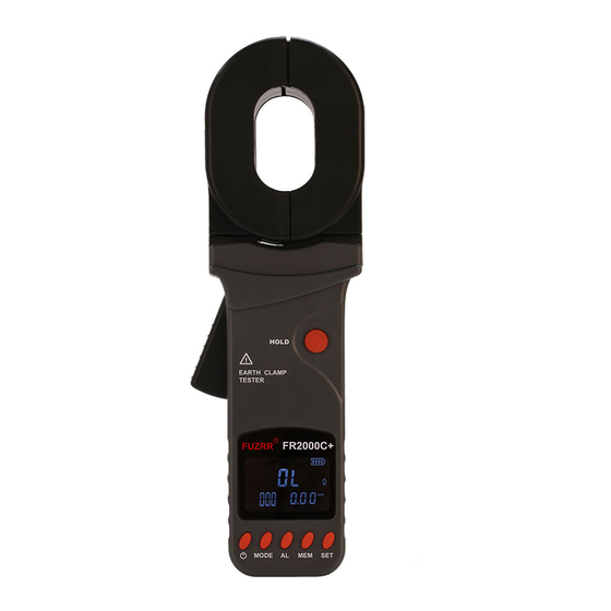
Ⅵ.Structure of Meter 1. Clamp Jaw 2. Trigger 3. LCD 4. POWER Key 5. MODE Key 6. AL Alarm Function Key 7. MEM Key 8. SET Key 9. HOLD Key 10.CALIBRATION LOOP:1Ω 11. CALIBRATION LOOP:10Ω VII. LCD Display... - Page 10 (1). Jaw Open Symbol (2). Alarm Symbol (3). Symbol of Greater Than (4). DC AC Symbol (5). Symbol of data access (6). Symbol of data memory (7). Noise signal (8). Data lock symbol (9). Symbol of battery (10). Resistance unit (11).
- Page 11 the symbol shows. At this point, trigger may be artificially pressed, or the jaws have been seriously polluted, and can no longer continue to measure. ⑵. “Er” Boot-strap error symbol, May be pressing trigger or jaw has been opened when the power is turn on. Symbol of low battery voltage: when the battery voltage ⑶.
-
Page 12: Ⅷ. Measuring Principle
VIII. Measuring Principle The basic principle of the ground resistance measurement of the clamp-type grounding resistance meter is to measure the loop resistance. See below. The jaw section of the clamp meter consists of a voltage coil and a current coil. The voltage coil provides the excitation signal and induces a potential V on the circuit under test. -
Page 13: Battery Voltage Check
Before booting up, the trigger should be pressed for a couple of times to ensure the jaws are well closed. Boot, must maintain clamp meter natural resting state, don’t flip Clamp, don’t be imposed outside force on the jaw, otherwise can not guarantee the accuracy of measurement Press the power button to switch on and off. -
Page 14: Resistance Test
3. Resistance Test When the user thinks that the grounded value does not conform to the normal, you can use a random calibration ring to check whether the clamp meter is normal. The check ring has two resistances of 1Ω and 10Ω. After the power-on self test is completed, the large middle digit shows “OLΩ”... -
Page 15: Clock Settings
Resistance + clock mode: The circuit of the measured resistance exceeds the lower limit, The number of save groups is 8 and the current time is 12:08 4.Clock Settings After power on, long press the "SET" button (more than 3 seconds) to enter the clock setting mode. -
Page 16: Date Lock
6.Date Lock After the measurement is stable after power on, short press “HOLD” key to lock the current display data, save the data, and press “HOLD” key again to exit lock mode. As shown below: 7.Data Storage / Review / Delete When the measurement is completed after power on, short press "HOLD"... -
Page 17: Ⅹ. Battery Instructions
In the data review state, long press the "SET" button, then press the "POWER" button to delete the stored data Ⅹ. Battery Instructions When the voltage drops to 5.2V, the battery symbol " " is displayed. Please replace the battery. Low battery voltage affects measurement accuracy. - Page 18 Where: R is the target grounding resistance. is the equivalent resistance of the other entire tower grounding resistances paralleled. Although strictly on the theoretical grounding, because of the existence of so-called "mutual resistance”, R is not the usual parallel value in the sense of electrical engineering (slightly higher than its IEC parallel output value).
- Page 19 the grounding resistance paralleled is calculated by the usual sense. Thus, for the grounding system of N (N is smaller, but larger than 2) grounding bodies, it can offer N equations: .. .....
- Page 20 solutions. In principle, in addition to ignoring the mutual resistance, this method does not have the measurement error caused by neglecting R However, users need to pay attention to that: in response to the number of the grounding bodies mutually linked in your grounding system, it is necessary to measure the same number of the testing values for calculating of the program, not more or less.
- Page 21 As the resistance value measured by the Meter is the value of the series resistance from the testing line and two grounding resistances. Where: R is the resistance value measured with the Meter. is the resistance value of the testing line. Meter can measure out the resistance value by connecting the test lines with both ends.
- Page 22 Second, have R and R linked up, as shown in the following figure. Use the Meter to get the second reading R Third, have R and R linked up, as shown in the following figure. Use the Meter to get the third reading R In the above three steps, the reading measured in each step is the value of the two series grounding resistance.
-
Page 23: Ⅻ. Accessories
As the reference points, the grounding resistance values of the other two grounding bodies are: RB=R1-RA RC=R3-RA ⅪI. Accessories Earth Tester Battery 5th alkaline battery 4PCS Test Loop Monitor software CD (FR2000C+) USB line(FR2000C+) User’s Manual 1SET Carrying Case... - Page 24 GuangZhou ZhengNeng Electronics Technology Co. Address: 2F, No.15 Baoshu Road, Taihe, Baiyun District, Guangzhou, Guangdong, China Toll-free call:4000-1515-38 Tel:86-20-36544172 Fax:86-20-37319075 Post:510540 WebSite:www.znele.com...
Need help?
Do you have a question about the FR2000+ and is the answer not in the manual?
Questions and answers