
Subscribe to Our Youtube Channel
Related Manuals for Digitimer D400

Summary of Contents for Digitimer D400
- Page 1 Digitimer Multi-channel 50/60Hz Mains Noise Eliminator OPERATOR’S MANUAL Two channel D400-2 Four channel D400-4 For Research Use Only “ Digitimer” is a registered trademark of Digitimer Limited...
- Page 2 Digitimer Ltd – D400 Operator’s Manual Version 1.2 Digitimer Limited 37 Hydeway Welwyn Garden City Hertfordshire AL7 3BE Tel: +44 (0)1707 328347 Fax: +44 (0)1707 373153 E-mail: sales@digitimer.com technical@digitimer.com Website: www.digitimer.com...
-
Page 3: Table Of Contents
Digitimer Ltd – D400 Operator’s Manual Version 1.2 Table of Contents D400 Intended Use & Description ..................6 Introduction ........................6 The Problem ........................6 Theory of Operation......................6 Unpacking the D400 ....................... 7 Supplied Accessories ......................7 Optional Accessories ......................8 Precautions and Warnings ..................... - Page 4 Mains Inlet, Fuse Holder & Power Switch ..............15 Voltage Selector ......................15 Potential Equalisation Connector (PEC) ................ 15 USB Socket ........................15 Installation & Use of the D400 ..................... 16 D400 Control Panel Software ....................17 Software Installation ......................17 Software GUI Controls ...................... 17 Third Party Software Control ....................
- Page 5 Digitimer Ltd – D400 Operator’s Manual Version 1.2 Product Registration Please take time out to register your new product. Details are included in the Introduction. You can even do it online at:- www.digitimer.com/register...
-
Page 6: D400 Intended Use & Description
The Digitimer D400 is a multi-channel, standalone, mains noise eliminator designed for real- time removal of 50/60Hz mains noise interference from amplified biological and other signals prior to acquisition by digital data recording systems. The D400 is unique as the first commercially manufactured, multi-channel, standalone noise eliminator and does not need to be operated in conjunction with any particular brand of data acquisition system. -
Page 7: Unpacking The D400
D400 have been developed wholly by Digitimer and are unique to this device. Not only does the D400 remove mains noise in the 50Hz to 60Hz frequency, but it is also effective at removing associated harmonics of these frequencies. Importantly, and unlike standard 50/60Hz notch filters, this method of noise removal is not detrimental to signals of interest, even if they lie within the 50-60Hz frequency range. -
Page 8: Optional Accessories
Digitimer Ltd – D400 Operator’s Manual Version 1.2 2 or 4 Channel Output Lead (male DB9 to multiple BNC): D990-33 (for D400-2) D990- 35 (for D400-4). Optional Accessories The following items are optional purchases available from Digitimer or our local representatives. -
Page 9: Contact Addresses
Please contact Digitimer for Representatives in other countries. Servicing & Maintenance This equipment does not require any regular maintenance but if you would like your D400 to be serviced we are happy to do so. Please contact us for a reference number and instructions before despatching the unit. -
Page 10: Environmental Considerations
Warranty Information Limited Warranty Digitimer Limited warrants to the first purchaser, for a period of one year from the date of purchase, that this Digitimer instrument (hereafter referred to as the “Product”) will be free from defective workmanship and materials, and agrees that it will, at its option, either repair the defect or replace the defective Product or part thereof at no charge to the purchaser for parts and labour. -
Page 11: Obtaining Warranty Service
This web address is your point of contact for all questions regarding the D400. The site’s contents are now growing rapidly, so please bookmark it so that you visit it regularly to check out the new items. -
Page 12: Specifications
Digitimer Ltd – D400 Operator’s Manual Version 1.2 Specifications Number of Channels: 2 (D400-2), 4 (D400-4) Working Input Voltage Range: ±10V Maximum Noise Amplitude: ±1V (pk-pk) Output Voltage Range: ±10V Frequency Response: DC to 1MHz (-3dB) Front Panel Controls: • CLEAR - Erases existing noise templates •... -
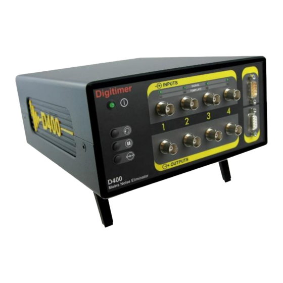
Page 13: Hardware Overview
Version 1.2 Hardware Overview The D400 is designed for ease of use, has very few controls and is essentially “plug and play”. There are three push buttons on the left of the front panel and to the right of these are multiple pairs of signal input and output connectors, as well as equivalent 9-way “D”... -
Page 14: Channel Status Led's
While the D400 is in the “Hold” mode, the TEMPLATE LED’s are AMBER. BYPASS This allows the user to see what the raw signal passing through the D400 looks like without any noise cancellation. When the D400 is in “Bypass” mode, the TEMPLATE LED’s are extinguished. -
Page 15: D400 Rear Panel Components
Earth/Ground reference for unit and bonding point. This is to be used when the earth/ground conductor in the mains lead cannot be relied upon. USB Socket Provides USB connection to host computer running Windows OS. USB connection allows:- Software control of D400 settings via Control Panel. Updates to firmware. Recalibration of the D400. -
Page 16: Installation & Use Of The D400
3. Connect the mains lead to the D400 rear panel mains inlet socket and power the unit on using the associated On/Off switch. If the D400 Control Panel Software is being used, double-click on the program shortcut to run it. -
Page 17: D400 Control Panel Software
4. Following installation, a D400 shortcut will be placed on the Windows desktop. 5. Connect the D400 to the host PC using supplied USB cable and power it on. 6. Double-click on the D400 desktop shortcut to run the D400 Control Panel Software. -
Page 18: Third Party Software Control
Digitimer Ltd – D400 Operator’s Manual Version 1.2 The software controls of the D400 are laid out in a grid, with Master Control (M) on the left and individual channel control labelled 1 and 2 (D400-2) or 1 to 4 (D400-4) in the additional columns of the grid. -
Page 19: References
Version 1.2 References As the D400 is a new product we do not have any publications that cite its use, however, if you publish research which has used the D400, please cite the Digitimer D400-2 or D400-4 in your methods section to help other researchers e.g. D400-2 Mains Noise Eliminator (Digitimer Ltd., Welwyn Garden City, UK). - Page 20 Digitimer Ltd – D400 Operator’s Manual Version 1.2 Digitimer Limited 37 Hydeway Welwyn Garden City Hertfordshire AL7 3BE Tel: +44 (0)1707 328347 Fax: +44 (0)1707 373153 E-mail: sales@digitimer.com technical@digitimer.com Website: www.digitimer.com File Reference: N:\Docs\Company\Manuals\D400\D400_Manual_v1.2.docx Last updated: 04/12/20...
Need help?
Do you have a question about the D400 and is the answer not in the manual?
Questions and answers