Table of Contents
Advertisement
Quick Links
Advertisement
Table of Contents

Related Manuals for KROHNE SU 501 Ex


Summary of Contents for KROHNE SU 501 Ex
- Page 1 Operating Instructions SU 501 Ex Signal conditioning instrument...
-
Page 2: Table Of Contents
9 Functional safety General......SU 501 Ex - Signal conditioning instrument... - Page 3 10.2 Dimensions ......10.3 Certificate ......SU 501 Ex - Signal conditioning instrument...
-
Page 4: About This Document
1 About this document 1.1 Function This operating instructions manual has all the information you need for quick setup and safe operation of SU 501 Ex. Please read this manual before you start setup. 1.2 Target group This operating instructions manual is directed to trained personnel. -
Page 5: For Your Safety
(e.g. the VDE regulations in Germany) as well as all prevailing safety regulations and accident prevention rules. 2.5 CE conformity SU 501 Ex is in CE conformity with EMC (89/336/EWG) and NSR (73/23/EWG). Conformity has been judged acc. to the following standards:... -
Page 6: Safety Information For Ex Areas
2.6 Safety information for Ex areas Please note the Ex-specific safety information for installation and operation in Ex areas. These safety instructions are part of the operating instructions manual and come with the Ex- approved instruments. SU 501 Ex - Signal conditioning instrument... -
Page 7: Product Description
Ex separating chamber with Ex version Socket Transparent cover 3.2 Principle of operation SU 501 Ex is a single signal conditioning instrument for Area of application processing of vibrating level switches. SU 501 Ex signal conditioning instrument can power connec- Physical principle ted instruments and process their measuring signals. -
Page 8: Adjustment
The integration time and the mode (A/B) can be preset on the signal conditioning instrument via a DIL switch block. A test key is lowered on the front plate of SU 501 Ex. When pushing the key, the measuring system is checked on correct function. -
Page 9: Mounting
SU 501 Ex signal conditioning instrument with plug-in socket Installation location for mounting on carrier rail acc. to EN 50022. The front plate of SU 501 Ex can be provided with a lockable Transparent cover transparent cover to protect the instrument against unautho- rised adjustment. - Page 10 With a SU 501 Ex in Ex version, the supplied coded pins (type coded pin and Ex coded pin) must be inserted by the user acc. to the below chart.
- Page 11 EEx ia Plug-in socket Typ 600-1 0...10V DISBUS Fig. 4: Plug-in socket SU 501 Ex Bridges for looping the power supply Type coding for SU 501 Ex Ex coding with Ex version Ex separating chamber SU 501 Ex - Signal conditioning instrument...
-
Page 12: Connecting To Power Supply
5.2 Connection procedure Move to electrical connection and proceed as follows: 1 Snap the socket without SU 501 Ex onto the carrier rail SU 501 Ex - Signal conditioning instrument... - Page 13 2 Connect sensor cable to terminal 1 and 2, and where applicable, connect the screen 3 Connect power supply (switched off) to terminal 9 and 10 4 Insert SU 501 Ex into the plug-in socket and screw it down tightly The electrical connection is finished.
-
Page 14: Wiring Plan
Connecting to power supply 5.3 Wiring plan 12 13 14 L1 N Fig. 5: Wiring plan SU 501 Ex Sensor Sensor input Transistor output Relay output Power supply SU 501 Ex - Signal conditioning instrument... -
Page 15: Set Up
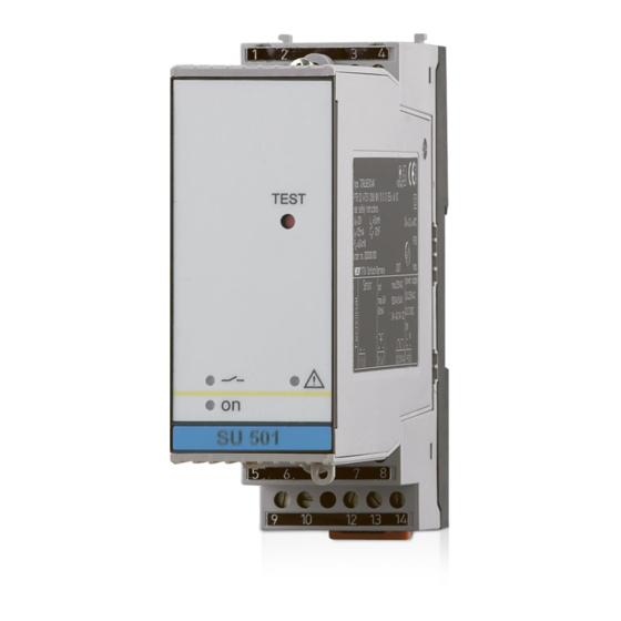
Test key Control lamp level relay (LED) Control lamp fail safe relay (LED) Control lamp power supply (LED) Ex separating chamber Terminal for probe Sockets for bridges Transistor output Relay output 10 Power supply SU 501 Ex - Signal conditioning instrument... -
Page 16: Adjustment Elements
Control lamps switching status and fault signal. Green - Operation control lamp - Mains voltage on, instrument operates - Failure lamp - Fault on the sensor circuit by sensor failure or line break SU 501 Ex - Signal conditioning instrument... - Page 17 (ze) and switch off delay (za) are switched on together, the adjusted time applies to both delay modes. Information: Keep in mind that the integration time of the sensor and signal conditioning instrument accumulate. SU 501 Ex - Signal conditioning instrument...
- Page 18 The following operating condi- tions are simulated during the test: Fault signal Empty signal Set alternately switch 2 and/or 3 to "on". The times apply to the adjusted delay mode. SU 501 Ex - Signal conditioning instrument...
- Page 19 Level relay deenergised Relay control Relay control lamp off lamp lights 3 Simulation of a full signal Failure lamp Failure lamp off Failure lamp off 4 Return to the current operating condition (covered/uncovered) SU 501 Ex - Signal conditioning instrument...
-
Page 20: Maintenance And Fault Rectification
Maintenance and fault rectification 7 Maintenance and fault rectification 7.1 Maintenance When used as directed in normal operation, SU 501 Ex is completely maintenance-free. 7.2 Fault rectification SU 501 Ex offers maximum reliability. Nevertheless faults can Causes of malfunction occur during operation. These may be caused by the following, e.g.:... - Page 21 2 If the red failure lamp continues to light, separate the sensor from the connection cable and connect a resistor of 1 kOhm instead on the signal conditioning instrument The signal conditioning instrument is defective if the failure lamp continues to light SU 501 Ex - Signal conditioning instrument...
- Page 22 Check the connection cable to the sensor 5 If the failure lamp continues to light, the signal conditioning instrument is defective Exchange signal conditioning instrument or return it for repair SU 501 Ex - Signal conditioning instrument...
-
Page 23: Instrument Repair
Print and fill out one form per instrument Clean the instrument and pack it damage-proof Attach the completed form and possibly also a safety data sheet to the instrument. SU 501 Ex - Signal conditioning instrument... -
Page 24: Dismounting
8.2 Disposal SU 501 Ex consists of materials which can be recycled by specialised recycling companies. We have purposely desig- ned the electronic modules to be easily separable. Mark the instrument as scrap and dispose of it according to government regulations (electronic scrap ordinance, …). -
Page 25: Functional Safety
Functional safety 9 Functional safety 9.1 General This safety manual applies to the SU 501 Ex signal Validity conditioning instrument. The instrument corresponds to a part system of type A. In combination with a vibrating level switch, the signal Area of application... -
Page 26: Planning
(MTTR = 8 h) If the demand rate is only once a year, then the measuring Low demand mode system can be used as safety-relevant subsystem in "low demand mode" (IEC 61508-4, 3.5.12). SU 501 Ex - Signal conditioning instrument... - Page 27 The processing unit must evaluate the output circuit of the Configuration of the proces- sing unit measuring system by taking the quiescent current principle into account. The processing unit must correspond to the SIL level of the measuring chain. SU 501 Ex - Signal conditioning instrument...
-
Page 28: Setup
The test must be carried out in a way that verifies the flawless operation of the safety functions in conjunction with all system components. SU 501 Ex - Signal conditioning instrument... -
Page 29: Safety-Related Characteristics
10 years function Single channel architecture The following characteristics are derived from the above mentioned data: SIL2 (Safety Integrity Level) HFT = 0 (Hardware Fault Tolerance) SU 501 Ex - Signal conditioning instrument... - Page 30 Proof recurring function test must be carried out. Proof Fig. 9: Time-dependent process of PFD after 1 year after 5 years after 10 years Numbers see in the above charts. SU 501 Ex - Signal conditioning instrument...
-
Page 31: Supplement
10 mV DC, max. 250 V AC, 250 V DC Switching current min. 10 µA DC, max. 3 A AC, 1 A DC Breaking capacitance max. 500 VA, max. 54 W DC SU 501 Ex - Signal conditioning instrument... - Page 32 (VDE 0106, part 1) between power supply, meas. data input, level relay and transistor output Approvals ATEX ATEX II (1) GD [EEx ia] IIC Others Deviating data with Ex applications: see separate safety instructions. SU 501 Ex - Signal conditioning instrument...
-
Page 33: Dimensions
Supplement 10.2 Dimensions 1 2 1 3 1 4 134mm (5 ") 36mm (1 ") Fig. 10: Dimensions SU 501 Ex Transparent cover Carrier rail 35x7.5 or 35x15 acc. to EN 50022 SU 501 Ex - Signal conditioning instrument... -
Page 34: Certificate
10.3 Certificate CE declaration of conformity Fig. 11: CE declaration of conformity SU 501 Ex - Signal conditioning instrument... - Page 35 SU 501 Ex - Signal conditioning instrument...
- Page 36 Subject to change without notice 27953-EN-050616...
Need help?
Do you have a question about the SU 501 Ex and is the answer not in the manual?
Questions and answers