Table of Contents
Advertisement
Quick Links
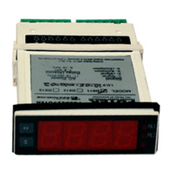
Where can I find the wiring guide for my display?
See "Connections" on page 1 of the Product Manual and the diagram below. Also, the
black and white wires from the power cord should be connected to pins 11 and 12. It is
not necessary to connect the green wire (ground) to the meter.
What do the buttons on the display do?
See "Keyboard Operation and Setup" on page 2 of the Product Manual.
What does each menu item do?
CAL – allows the user to scale the meter for the sensor
dECP – allows the user to choose desired position of the decimal point
U Lo – allows the user to input the low input signal (mV/V)
U Hi – allows the user to input the high input signal (mV/V)
rdLO – allows the user to input the desired display value corresponding to the
low input signal
rdHi – allows the user to input the desired display value corresponding to the
high input signal
Ky 1 – allows the user to choose a function for key 1
AL1 – sets key 1 as an alarm
PEAK – sets key 1 as a peak switch
TArE – sets key 1 as a tare switch
Ky 2 – allows the user to choose a function for key 2
AL2 – sets key 2 as an alarm
PEAK – sets key 2 as a peak switch
TArE – sets key 2 as a tare switch
GrnE – sets key 2 as a switch between gross values and net values
10 Thomas, Irvine, CA 92618 USA T (949)-465-090 F (949)-465-0905
IPM300 FAQ's
futek@futek.com
www.futek.com/support
Advertisement
Table of Contents

Related Manuals for Futek IPM300

Summary of Contents for Futek IPM300
- Page 1 IPM300 FAQ’s Where can I find the wiring guide for my display? See “Connections” on page 1 of the Product Manual and the diagram below. Also, the black and white wires from the power cord should be connected to pins 11 and 12. It is not necessary to connect the green wire (ground) to the meter.
- Page 2 Scroll through the menu by pressing the bottom button. The options are below: ‘GrOS’ – Gross value ‘nEt’ - Net value ‘ntrS’ - Net value since last autozero 10 Thomas, Irvine, CA 92618 USA T (949)-465-090 F (949)-465-0905 futek@futek.com www.futek.com/support...
- Page 3 Press the top button until the display returns to your pass-code function. Press the bottom 10 Thomas, Irvine, CA 92618 USA T (949)-465-090 F (949)-465-0905 futek@futek.com www.futek.com/support...
- Page 4 This calibration option is located under the ‘SPEC’ menu. Note: Display will automatically exit setup mode and return to run mode if a button is not pushed within 30 seconds. 10 Thomas, Irvine, CA 92618 USA T (949)-465-090 F (949)-465-0905 futek@futek.com www.futek.com/support...
- Page 5 Press the top button and the meter will activate the calculations and go through the reset procedure. The unit is now ready to use. For more information, see “Automatic Calibration” on page 5 of the Product Manual. 10 Thomas, Irvine, CA 92618 USA T (949)-465-090 F (949)-465-0905 futek@futek.com www.futek.com/support...
Need help?
Do you have a question about the IPM300 and is the answer not in the manual?
Questions and answers