Table of Contents
Advertisement
Feb. 2010
Table of Contents
Cautionary Notes ..............................................................2
Specifications .....................................................................3
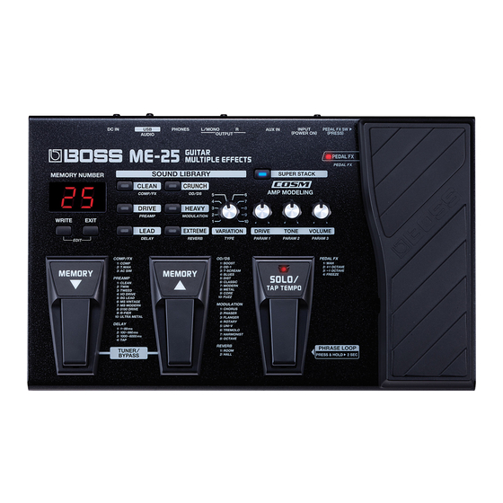
Location of Controls .........................................................5
Exploded View ..................................................................6
Exploded View Parts List.................................................7
Important Notes When Replacing Parts ........................8
Parts List .............................................................................9
Verifying the Version Number......................................11
Copyright © 2010 Roland Corporation
All rights reserved. No part of this publication may be reproduced in any form without the written permission
of Roland Corporation.
Data Backup and Restore Operations ..........................11
Performing a Factory Reset............................................11
Updating the System ......................................................12
Test Mode .........................................................................13
Block Diagram .................................................................18
Circuit Board (Main Board) ...........................................20
Circuit Diagram (Main Board: Analog) .......................22
Circuit Diagram (Main Board: Digital) ........................24
17058662E0
SERVICE NOTES
Issued by RJA
ME-25
CC-KWS
Advertisement
Table of Contents

Related Manuals for Roland ME-25


Summary of Contents for Roland ME-25
-
Page 1: Table Of Contents
Circuit Diagram (Main Board: Analog) .......22 Verifying the Version Number........11 Circuit Diagram (Main Board: Digital) ......24 Copyright © 2010 Roland Corporation All rights reserved. No part of this publication may be reproduced in any form without the written permission of Roland Corporation. -
Page 2: Cautionary Notes
Right dot: This indicates that calibration has been executed by the The power to the ME-25 comes on when a plug is connected to the INPUT jack. user one or more times. Before making the connection, be sure to lower the volume level on the * This history cannot be reset. -
Page 3: Specifications
CHORUS 24-bit + AF method PHASER * AF method (Adaptive Focus method) FLANGER This is a proprietary method from Roland & BOSS that vastly improves the ROTARY signal-to-noise (S/N) ratio of the A/D and D/A converters. UNI-V TREMOLO DA Conversion... - Page 4 * 0 dBu = 0.775 Vrms * Printed matters will not be supplied after the end of the production. Then, download the electronic file from the Roland web site. * In the interest of product improvement, the specifications and/or appearance of...
-
Page 5: Location Of Controls
Feb. 2010 ME-25 Location of Controls fig.Panel.eps Part Code Part Name Description Q’ty until B**1349 5100012842 7 SEG COVER PRINT 5100001581 A-552SR-A B/W (F5029412R0) 7-segment LED 05015956 L-7104SRT (F5229820R0) lamp type from B**1350 5100002398 7 SEG COVER (G2567172R0) 5100001581 A-552SR-A B/W (F5029412R0) -
Page 6: Exploded View
Feb. 2010 ME-25 Exploded View fig.Bunkaizu.eps... -
Page 7: Exploded View Parts List
Feb. 2010 ME-25 Exploded View Parts List Part Code Part Name Description Q’ty 5100011390 TOP COVER 5100011391 BOTTOM COVER 5100011392 VR PEDAL 5100011395 PEDAL PLATE 5100011394 PEDAL HOLDER 5100011393 KEY UNIT 5100012842 7 SEG COVER PRINT until B**1349 5100002398 7 SEG COVER... -
Page 8: Important Notes When Replacing Parts
Feb. 2010 ME-25 Important Notes When Replacement of the Key Unit Replacing Parts For the Key Unit as well, the part code before and after modification is unchanged (#5100011393). To distinguish the new and old items, refer to the following figures. -
Page 9: Parts List
Feb. 2010 ME-25 Parts List fig.-part1-e.eps Due to one or more of the following reasons, Safety Precautions: parts with parts code ******** cannot be supplied as service parts. The parts marked have safety-related characteristics. Use only listed parts for replacement. - Page 10 Feb. 2010 ME-25 SCREWS 40013056 SCREW M3X6 PAN MACHINE W/SW+PW(S) ZC 40342956 SCREW M3X6 PAN MACHINE W/SW+PW(S) BZC 40011278 SCREW 3X8 BINDING TAPTITE P FE ZC 40011312 SCREW 3X8 BINDING TAPTITE P FE BZC 40019123 SCREW 3X8 BINDING TAPTITE S BZC...
-
Page 11: Verifying The Version Number
A Factory Reset in the User Mode (Owner’s Manual p. 12) must not be Turn down all controls all the way counterclockwise (minimum). executed on a user’s ME-25 in your care. When executing the Factory Reset, be Hold down [WRITE] and [EXTREME] and insert a plug into the INPUT sure to follow the procedure described below. -
Page 12: Updating The System
Updating the System You use a computer-based MIDI sequencer or the like to play back update-use MIDI data, and carry out a system update on the ME-25 by receiving the sent MIDI data. Performing a system update causes any patch data in the unit to be lost. Back up any necessary data in advance as described in Data Backup and Restore Operations (p. -
Page 13: Test Mode
• Tool for switching the input to the INPUT jack (e.g., J-5 or the like) • AA batteries x 6 • Computer (running Windows XP) • USB driver for the ME-25 (obtainable from http://www.roland.co.jp) * Install the USB driver into the computer in advance. Entering the Test Mode Refer to the figure below and connect the measuring equipment to connectors other than the INPUT jack. - Page 14 Feb. 2010 ME-25 Quitting the Test Mode 2. Current-consumption Check, Voltage detection Check, and SW (Switch) and Detach the plug from the INPUT jack, switch off the power. LED Check Make sure that all LEDs light up. Skipping Measure the current consumption and verify that it is between 110 and Press and hold down [CRUNCH] and [SUPER].
- Page 15 * This calibration record cannot be reset. The ME-25 records the expression-pedal calibration history. Executing this in the User Mode (Owner’s Manual p. 12) overwrites the calibration record left by the user.
- Page 16 Feb. 2010 ME-25 11. Verify that nothing is output from the OUTPUT L, R. 5. D/A Check fig.test5-5.eps Insert plugs into the OUTPUT L/MONO, R and PHONES jacks. * Correct waveforms are not displayed unless all connections are made to the OUTPUT L/MONO, R and PHONES jacks.
- Page 17 ME-25. From the Start menu, select Settings, then Control Panel, then Sounds and Audio Devices. At the Audio tab, make sure the ME-25 can be selected. Detach the plug from AUX IN jack, connect the monitor speakers to OUTPUT L, R, and verify that no sound is heard.
-
Page 18: Block Diagram
Feb. 2010 ME-25 Block Diagram fig.Block.eps@L PSA–XXX INPUT BATT LR6 SizeAA *6 DeEnpha PreEnpha CODEC Analog +9V BATTERY DET / AFAD AK4552 Digital +5V AIN5 Digital +1.5V DC–DC IC15 Digital +3.3V RESET IC TUSB X’tal X1 AIN6 LED * 3... - Page 19 Feb. 2010 ME-25 fig.Block.eps@R AUX IN PHONES OUTPUT L OUTPUT R Mute EEP–ROM IC5 (64kbit for T USB) X’tal X2 M IC13 or ESC)
-
Page 20: Circuit Board (Main Board)
Feb. 2010 ME-25 Circuit Board (Main Board) fig.b-Main-1.eps... - Page 21 Feb. 2010 ME-25 fig.b-Main-2.eps...
-
Page 22: Circuit Diagram (Main Board: Analog)
Feb. 2010 ME-25 Circuit Diagram (Main Board: Analog) fig.d-Main-Analog.eps@L A+3.3 Analog AVCC TP32 TP31 IC17 NJM2115V(TE1) C119 0.1uF A+3.3 TP107 TP12 D ( 0.5% ) TP93 TP17 TP158 INPUT C132 TP168 D ( 0.5% ) 10pF R107 R127 TP40 TP29... - Page 23 Feb. 2010 ME-25 fig.d-Main-Analog.eps@R TP187 TP150 TP144 1800pF D ( 0.5% ) Gain = +6.336dB C169 OUT L(MONO) D ( 0.5% ) UnPop TP30 UnPop TP145 C163 TP180 TP177 TP148 TP189 C155 C157 22uF 22uF IC16 D ( 0.5% )
-
Page 24: Circuit Diagram (Main Board: Digital)
Feb. 2010 ME-25 Circuit Diagram (Main Board: Digital) fig.d-Main-Digital.eps@L TC4W66FU(TE12L,F) IC9 D+3.3 D+3.3 D+3.3 Digital R162 TP244 TP229 C167 10uF TC4W66FU(TE12L,F) LRCK R148 0.1uF D+5V TP230 TP210 0.1uF R163 VBUS USB SECTION 0.1uF 0.1uF D+3.3 TC7S08FU(TE85L.F) C126 UnPop TP241 0.1uF 0.1uF... - Page 25 Feb. 2010 ME-25 fig.d-Main-Digital.eps@R D+3.3 SW SECTION SKQKAKD010 SKQKABD010 SKQKABD010 SKQKABD010 SKQKABD010 E85L.F) RTA03-4D101JTP SWDATA(0) SWDATA(1) SWDATA(2) SWDATA(3) D+3.3 SWDATA(4) SWDATA(5) SWDATA(6) SWDATA(7) SW10 SWDATA(8) IC12 SKQKABD010 SKQKABD010 SKQKABD010 SKQKAKD010 SKQKABD010 SWDATA(11) TC7W04FU(TE12L.F) SWDATA(10) SWDATA(9) RA17 RTA03-4D101JTP RA21 RTA03-4D101JTP D+3.3 D+1.5...
Need help?
Do you have a question about the ME-25 and is the answer not in the manual?
Questions and answers