
Subscribe to Our Youtube Channel
Related Manuals for Soredex DIGORA Optime DXR-50 001


Summary of Contents for Soredex DIGORA Optime DXR-50 001
- Page 1 DIGORA Optime DXR-50 001 ® Digital intraoral imaging plate system User’s Manual Document no. rev. 2 (0908) 204253...
- Page 3 This unit is marked according to the Medical Device Directive 93/42/EEC (if the unit contains the CE mark) Document number 204253 rev. 2 (0908) Original approved English language version Manufactured by SOREDEX P.O. BOX 148 FIN-04301 TUUSULA, FINLAND Tel. +358 (0)10 270 2000 Fax.
- Page 4 Imaging plate unit Soredex endeavours to produce product documentation that is accurate and up to date. However, our policy of continual product development may result in changes to products that are not reflected in the product documentation. There- fore, this document should not be regarded as an infallible guide to current product specifications.
-
Page 5: Table Of Contents
Imaging plate unit Contents 1. The DIGORA® Optime..............1 1.1 Introduction ....................1 1.2 System installation ..................2 Positioning the unit ................... 2 Positioning the PC ..................3 Other devices ................... 3 2. Intraoral imaging plate unit ............... 4 2.1 Main parts and controls ................4 2.2 Accessories .................... - Page 6 Imaging plate unit 3. Setup options ................. 24 3.1 Tooth numbering ..................24 Selecting the tooth numbering feature ............. 24 Using the tooth numbering feature ............24 3.2 Resolution ....................25 3.3 Image Processing ..................25 4. Handling and care of imaging plates..........26 4.1 General .....................
-
Page 7: The Digora Optime
DIGORA Optime digital imaging plate unit ® (the unit). SOREDEX dental Imaging Plates (IPs), protective covers, hygiene bags and other related imaging plate accessories. A PC (not supplied) in which suitable dental imaging software. A local area network (LAN) cable (not supplied) will be required if the system is to be used in a network. -
Page 8: System Installation
Imaging plate unit Introduction NOTES: Only personnel trained and authorized by the manufacturer of the unit are allowed to install and configure the unit. Only use the imaging plates, protective covers and hygiene bags supplied by the manufacturer of the unit. Please read the section 7. -
Page 9: Positioning The Pc
Introduction Imaging plate unit Positioning the PC The PC connected to the unit should not be used in the patient environment. The minimum horizontal distance between the patient and the PC is 1.5 m (4.5 ft). The minimum vertical distance between the patient and the PC is 2.5 m (6.5 ft). -
Page 10: Intraoral Imaging Plate Unit
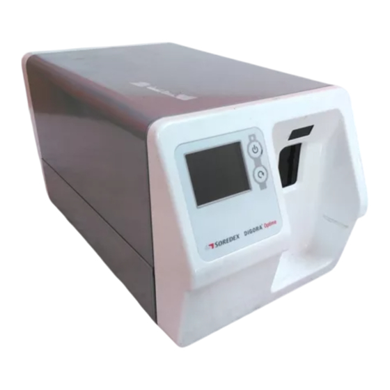
Imaging plate unit 2. Intraoral imaging plate unit 2. Intraoral imaging plate unit 2.1 Main parts and controls User’s manual 204253... -
Page 11: Accessories
2. Intraoral imaging plate unit Imaging plate unit 2.2 Accessories For additional information about the accessories listed below contact your authorized dealer. Not all accessories are available for all units. Imaging plates (IPs). Equivalent to film sizes 0, 1, 2 and 3. - Page 12 Imaging plate unit 2. Intraoral imaging plate unit CAUTION: For optimum performance only use IPs, protective covers and hygiene bags supplied by the manufacturer of the unit or the manufacturer’s authorized distributors. The manufacturer will not be held responsible for problems caused by using accessories from other manufacturers.
-
Page 13: Display Symbols And What They Mean
2. Intraoral imaging plate unit Imaging plate unit 2.2 Display symbols and what they mean During use symbols and animations will appear on the unit display. These: indicate the status of the unit help you to operate the unit correctly show user mistakes and corrective actions display error codes display a preview image... - Page 14 Imaging plate unit 2. Intraoral imaging plate unit Imaging plate Yellow: wrong way round, rotate Protective cover Remove / disconnect Insert / connect Busy Unit in operation. Unit in erasing mode Check Something wrong or take alternative action. User’s manual 204253...
- Page 15 2. Intraoral imaging plate unit Imaging plate unit Dental imaging software Software not open, not ready or waiting for user action. Unit connection Not connected or connection not working. Rotate Error state and error number Check documentation supplied with the unit Unit in service mode (Service technicians only) User’s manual 204253...
-
Page 16: Using The System
Imaging plate unit 2. Intraoral imaging plate unit 2.3 Using the system For optimum performance only use IPs, protective covers and hygiene bags designed for this unit and supplied by authorized distributors. The manufacturer of this unit will not be held responsible for any problems caused by using accessories from other manufacturers. -
Page 17: Preparing An Ip For Exposure
2. Intraoral imaging plate unit Imaging plate unit When the status light turns green and ready animation, indicating IP insertion, appears on the unit display, the unit is ready to use (in the ready state). NOTE: If the ready animation does not appear, check the system setup described in the installation instructions. - Page 18 Imaging plate unit 2. Intraoral imaging plate unit 3. Turn the protective cover and IP over so that the black side of the protective cover is uppermost. This makes it easier to slide the protective cover and IP into the hygiene bag. 4.
-
Page 19: Imaging Plate Holders
2. Intraoral imaging plate unit Imaging plate unit Imaging plate holders It is recommended that imaging plate holders be used to ensure accurate IP positing and consistently good images quality. Using imaging plate holders improves image quality because: the IP is positioned correctly in relation to the tooth there is no positioning guesswork the IP is not bent and thus distortion is eliminated the IP cannot move in relation to the X-ray unit... -
Page 20: Taking An Exposure
Imaging plate unit 2. Intraoral imaging plate unit Taking an exposure 1. Place the IP, in its sealed hygiene bag, into the appropriate imaging plate holder and then insert it into the patient’s mouth in the position for the image you wish to take. 7uj7uj7 Note that the back of the sealed hygiene bag, the black side, must face the X-ray source. - Page 21 2. Intraoral imaging plate unit Imaging plate unit If the exposure time is too short images will be noisy. Such images may still usable for somediagnostic purposes. If the exposure time is too long images will be too uj7uj dark or will show patient movement. These images will not be good enough for accurate diagnostic examination.
-
Page 22: Reading An Imaging Plate
Imaging plate unit 2. Intraoral imaging plate unit Reading an imaging plate Single user configuration NOTE: If the unit is operated in a multiconnect configuration, please refer to Multiconnect configuration first to reserve the scanner. 1. Pull the flap to open the hygiene bag. 2. - Page 23 2. Intraoral imaging plate unit Imaging plate unit As soon as the protective cover is removed the unit detects that the IP is in the unit door and will switch from the standby state to the ready state (ready to use) and automatically slide the IP into the unit.
- Page 24 Imaging plate unit 2. Intraoral imaging plate unit CAUTION: If the metal disk on the rear of the IP can be seen on the digital image, it indicates that the IP was exposed from the wrong side. CAUTION - RETRIEVING IMAGES If the image is not transferred to the PC because of a network, PC or software failure, the image can be retrieved from the unit’s memory as long...
-
Page 25: Multiconnect Configuration
2. Intraoral imaging plate unit Imaging plate unit Multiconnect configuration 1. PC: To reserve the unit click the GREEN multiconnect icon, which is in the bottom right- hand corner of the PC display. The Connect window will appear. 2. PC: In the Connect window click the Reserve the Scanner button to reserve scanner. -
Page 26: Removing Ips From The Plate Collector
Imaging plate unit 2. Intraoral imaging plate unit 3. PC: To release the unit click the GREEN multiconnect icon and then click the Free the scanner (unit) button. Removing IPs from the plate collector When removing IPs from the plate collector hold them by their edges. -
Page 27: Retrieve Last Image
2. Intraoral imaging plate unit Imaging plate unit Retrieve last image If the last image read is not transferred to the PC because of a network, communication, PC or software failure, the last image read can be retrieved. IMPORTANT NOTE The LAST read image can only be retrieved if the unit is left on. -
Page 28: Shutting Down The Unit
Imaging plate unit 2. Intraoral imaging plate unit Shutting down the unit 1. Press and hold power on / off key until the indicator light goes off. NOTE: If there is an untransferred image in the unit’s memory the unit cannot be shut down. The image must be transferred first. -
Page 29: Errors
2. Intraoral imaging plate unit Imaging plate unit NOTE: It may take longer to erase IPs using the erasing mode than the normal read and erase mode. This is to ensure that IPs that have not been used recently are erased properly. 3. -
Page 30: Setup Options
Imaging plate unit 3. Setup options 3. Setup options There are several setup options in the dental imaging software that allow you to set the image quality to your requirements. To select the setup options: 1. From the dental imaging software you are using select Setup >... -
Page 31: Resolution
3. Setup options Imaging plate unit 3.2 Resolution 1. In the Image Scanning section, select either Super or High (default). Super gives a pixel size of 35μ. This results in images with better resolution, but more memory is required as the image files are larger. High a pixel size of 64μ. -
Page 32: Handling And Care Of Imaging Plates
Imaging plate unit 4. Handling and care of imaging plates 4. Handling and care of imaging plates The correct use, handling, cleaning and storage of imaging plates guarantees the best image quality and maximum service life of the imaging plates. 4.1 General •... -
Page 33: Cleaning
4. Handling and care of imaging plates Imaging plate unit • Unprotected IPs must not come in contact with the patient, the patient’s saliva or any other bodily fluids. Always use hygiene bags and protective covers with IPs when taking exposures to: - eliminate cross contamination - maintain image quality - maximize IP service life. -
Page 34: Storage
Imaging plate unit 4. Handling and care of imaging plates 4.4 Storage • Unpacked, exposed to ambient light in the dedicated storage box • Below 33°C / 80% RH and shielded from X-rays and ultraviolet radiation. • If an IP is stored for over 24 hours in a hygiene bag or in a location that is shielded from ambient light, the IP must be erased, to remove any potential fogging, before being used to take an... -
Page 35: Unit Care And Maintenance
5. Unit care and maintenance Imaging plate unit 5. Unit care and maintenance WARNING Switch the unit off and disconnect it from the main power supply before cleaning or disinfecting the unit. Do not allow liquids to enter the unit. 5.1 Cleaning the unit Use a non abrasive cloth moistened with either: - cool or lukewarm water,... -
Page 36: Maintenance
Imaging plate unit 5. Unit care and maintenance 5.3 Maintenance The unit does not require any maintenance. 5.4 Repair If the unit is damaged or malfunctions in any way it must only be repaired by service personnel author- ized by the manufacturer of the unit. 5.5 Disposal At the end of the useful working life of the unit and/or its accessories make sure that you follow national and... -
Page 37: Symbols That Appear On Or In The Unit
6. Symbols that appear on or in the unit Imaging plate unit 6. Symbols that appear on or in the unit DANGEROUS VOLTAGE LASER RADIATION IMPORTANT INFORMATION (Refer to user’s manual) Direct current Eternet connector RJ45 straight cable CE (0537) Symbol MDD 93/42/EEC This unit is marked according to the Medical Device Directive 93/42/EEC (if the unit contains the CE mark) -
Page 38: Warnings And Precations
Imaging plate unit 7. Warnings and precations 7. Warnings and precations THE UNIT IS A CLASS 1 LASER PRODUCT Note! When covers are removed the unit is a class 3B laser product – avoid exposure to the laser beam. CAUTION - Use of controls or adjustments or performance of procedures other than those specified herein may result in hazardous laser radiation exposure •... - Page 39 7. Warnings and precations Imaging plate unit • Unit not suitable for use in the presence of flammable anaesthetic mixture with air or with oxygen or nitrous oxide. • For ethernet connections, use an unshielded CAT6 LAN cable, so that multiple chassis must not be connected! The PC / Ethernet switch to which unit is connected to, should be approved appropriately (e.g.
- Page 40 Imaging plate unit 7. Warnings and precations User’s manual 204253...
-
Page 41: Appendix A. Technical Specifications
A. Technical Specifications Imaging plate unit Appendix A. Technical Specifications A.1 Unit Intraoral imaging plate unit DXR 50 Classification - Class 1 or 2 equipment depending on the classification IEC60601-1 of the PSU. No applied part - Continuous operation - IPX0 (enclosed equipment without protection against ingress of liquids Laser Safety Classification CLASS 1 LASER PRODUCT EN 60825-1 :2007... - Page 42 Imaging plate unit A. Technical Specifications A.2 Imaging Plates and hygiene bags Imaging plates (IP) Size Size 0 Size 1 Size 2 Size 3 Dimensions (mm) 22 x 31 24 x 40 31 x 41 27 x 54 Image size (pixels), 35 µm 628 x 885 685 x 1143 886 x 1171...
- Page 43 A. Technical Specifications Imaging plate unit A.3 Main dimensions User’s manual 204253 A - 3...
- Page 44 Imaging plate unit A. Technical Specifications Guidance and manufacturer’s declaration – electromagnetic emissions T he DXR-50 is intended for use in the electromagnetic environment specified below. The customer or the user of the DXR -50 should assure that it is used in such an environment. Emissions test Compliance Electromagnetic environment - guidance...
- Page 45 A. Technical Specifications Imaging plate unit Guidance and manufacturer’s declaration – electromagnetic immunity T he DXR-50 is intended for use in the electromagnetic environment specified below. The customer or the user of the DXR -50 should assure that it is used in such an environment. Immunity test IEC 60601 test level Compliance level...
- Page 46 Imaging plate unit A. Technical Specifications Guidance and manufacturer’s declaration – electromagnetic immunity The DXR-50 is intended for use in the electromagnetic environment specified below. The customer or the user of the DXR-50 should assure that it is used in such an environment. Immunity IEC 60601 test Compliance...
- Page 47 A. Technical Specifications Imaging plate unit Recom mended separation distances between portable and mobile RF communications equipment and the D XR-50. The DXR-50 is intended for use in an electromagnetic environment in which radiated RF disturbances are controlled. The customer or the user of the DXR -50 can help prevent electromagnetic interference by maintaining a minimum distance between portable and mobile RF communications equipment (transmitters) and the DXR-50 as recommended below, according to the maximum output power of the communications equipment.
- Page 48 Imaging plate unit A. Technical Specifications A - 8 User’s manual 204253...
-
Page 49: Appendix B. Installation And Setup
B. Installation and setup Imaging plate unit Appendix B. Installation and setup Installation and setup must only be carried out by service personnel trained and approved by the manufacturer of the unit. 1. System installation Positioning the unit Position the unit on a stable flat surface so that vibrations will not degrade the image quality. - Page 50 Imaging plate unit B. Installation and setup Other devices DO NOT connect any other devices to the unit or the PC(s) connected to the unit that are: not part of the supplied system not supplied by the manufacturer of the unit not recommended by the manufacturer of the unit.
- Page 51 B. Installation and setup Imaging plate unit 5. PC: From the scanner setup window select the Settings tab to open the Scanner Connection page. 6. PC: Select Direct Connection. Key the serial number of the unit into the Scanner serial number field. The serial number of the unit will appear on the unit display when the unit is switched on.
- Page 52 Imaging plate unit B. Installation and setup 7. PC: If the unit is to be used with several PCs select the Use Multi-Connect check box. and select a unique Workstation identifier number (between 1 and 8), for the PC being configured, from the drop down list.
- Page 53 B. Installation and setup Imaging plate unit 9. Repeat the above process for all the other PCs in the network. Make sure that you give each PC a different Workstation identifier. 10. Check the installation by starting image capture using the imaging software. If the Use Multi-Connect was selected the Workstation identifier of the PC (1 - 8) being used will appear on the unit display.
- Page 54 Imaging plate unit B. Installation and setup Obtain an IP address for the unit from your network administrator and key it into the IP field in the Scanner IP address area. NOTE! The PC and the unit must be in the same subnet when setting the IP address of the unit.
- Page 55 B. Installation and setup Imaging plate unit 3. Troubleshooting PROBLEM The unit does not come on. The unit’s power on / off status light and display are off. CAUSE / SOLUTION The main power supply to the unit is off or the unit is not switched on.
- Page 56 Imaging plate unit B. Installation and setup PROBLEM The IP-connection between the unit and the PC does not work. CAUSE / SOLUTION Check that the Direct connection method was configured correctly. If all the setting are correct but the connection still does not work, use the IP connection method.
- Page 57 B. Installation and setup Imaging plate unit PROBLEM Local area network / subnet configuration problem CAUSE / SOLUTION If the Dental imaging software animation (flashing yellow) appears and cable(s) / router(s) are known to be okay ask your network administrator for assistance. ii.
- Page 58 Imaging plate unit B. Installation and setup ii. Cabling not correct (link not active), and the Unit connection animation appears on the unit display. The unit is not physically connected to the PC. Connect the unit to the PC. iii. The PCs Ethernet connector(s) is faulty. There is usually a green link LED near the PCs Ethernet connector(s) on the NIC.
Need help?
Do you have a question about the DIGORA Optime DXR-50 001 and is the answer not in the manual?
Questions and answers