Table of Contents
Advertisement
Quick Links
Advertisement
Table of Contents

Subscribe to Our Youtube Channel
Related Manuals for Lowenstein Medical VENTIremote

Summary of Contents for Lowenstein Medical VENTIremote
- Page 1 EN Instructions for Use VENTIremote alarm Remote alarm case...
-
Page 2: Table Of Contents
Contents Contents Introduction 1.1 Intended use ........................ 4 1.2 Description of function ....................4 1.3 Compatibility ....................... 4 Safety 2.1 Safety information ......................5 2.2 General information ..................... 5 2.3 Safety information in these instructions ................ 6 Overview 3.1 Overview of remote alarm case ..................7 3.2 Display film ........................ - Page 3 Contents 10 Annex 10.1 Technical specifications ..................... 21 10.2 Safety distances ......................22 10.3 Markings and symbols ....................22 10.4 Standard scope of delivery ..................23 10.5 Accessories and spare parts ..................24 10.6 Warranty ........................24 10.7 Declaration of Conformity ..................25...
-
Page 4: Introduction
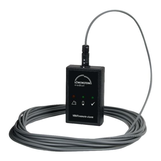
1.2 Description of function VENTIremote alarm is connected to the device via a cable (10 m and 30 m long). If the device issues alarms, VENTIremote alarm converts these into visual and acoustic signals and outputs them. -
Page 5: Safety
Individuals may be injured if the product is damaged or its function is impaired. Ensure that the VENTIremote alarm is free-standing and not covered up, otherwise alarm volume is reduced. This can lead to a risk to the patient and to damage to the device. -
Page 6: Safety Information In These Instructions
Safety • In the EU: As a user and/or patient, you must report any serious incidents occurring in conjunction with the product to the manufacturer and to the responsible authority. 2.3 Safety information in these instructions Indicates an unusually significant hazardous situation. If you ignore this instruction, severe irreversible or fatal injuries may result. -
Page 7: Overview
This is where the ODU connector (two white arrows) of the cable is connected to the VENTIremote alarm. 2 Stand-by indicator This green LED indicates that the VENTIremote alarm is working correctly. 3 Battery indicator If this yellow LED flashes, the battery needs changing. - Page 8 1 ODU connector This connects the cable to the VENTIremote alarm. 2 Cable This cable passes device alarms on to the VENTIremote alarm. 3 HRS connector This connects the cable to the device. 3.1.2 Cable for VENTIlogic LS/VENTIlogic plus series, prisma CHECK 1 ODU connector This connects the cable to the VENTIremote alarm.
-
Page 9: Display Film
Overview 3.2 Display film SYMBOL MEANING Red LED on: Alarm Yellow LED flashing every six seconds: Battery almost dead Stand-by indicator: The green LED must light briefly every six seconds during operation. -
Page 10: Preparation And Operation
Preparation and operation 4 Preparation and operation 4.1 Before operating for the first time Before you can operate the VENTIremote alarm, you must insert the U9VL-BP-type battery included in the scope of delivery. 1. Open the battery compartment. 2. Connect the battery to the connecting cables. - Page 11 Ensure that the connecting cables are underneath the battery in the battery compartment, so that the connecting cables are not trapped when the battery compartment is closed. 4. Push the battery compartment cover closed until it engages with an audible click. The VENTIremote alarm is now ready for operation.
-
Page 12: Setting Up And Connecting The Device
1. Place the VENTIremote alarm on a level surface. Warning! Ensure that the VENTIremote alarm is free-standing and not covered, otherwise alarm volume will be reduced. This can lead to a risk to the patient and to damage to the device. - Page 13 Preparation and operation 3. Connecting to prisma CHECK: Connect the bayonet connector to the remote alarm connection of the device. 4. Connecting to VENTIlogic LS/VENTIlogic plus series: Connect the bayonet connector to the remote alarm connection of the device.
-
Page 14: Operation With The Therapy Device
4.3 Operation with the therapy device 4.3.1 Switching on the VENTIremote alarm The VENTIremote alarm is switched on as soon as it is connected to the device by the cable. The stand-by indicator (green LED) on the VENTIremote alarm comes on briefly every six seconds during operation to indicate operational readiness. -
Page 15: Changing The Battery
VENTIremote alarm. 4.4 Changing the battery The VENTIremote alarm is operated with a battery of the U9VL-BP type. As soon as the battery indicator (yellow LED) comes on every six seconds and an acoustic alarm is issued every six seconds, the battery of the VENTIremote alarm must be replaced. - Page 16 Preparation and operation 4. Put the battery and the connecting cables in the battery compartment. Notice! Ensure that the connecting cables are underneath the battery in the battery compartment, so that the connecting cables are not trapped when the battery compartment is closed.
-
Page 17: Hygiene Treatment
5.1 Cleaning Caution! The VENTIremote alarm must be completely dry before being started up. Wipe the VENTIremote alarm and the cable with a soft, damp cloth. 5.2 Disinfection If required, e.g. following infectious diseases or unusual contamination, you can also disinfect the housing of the VENTIremote alarm and the cable. -
Page 18: Function Check
Ensure that the connector engages correctly in the socket. If you find faults during the function check, you may not use the VENTIremote alarm. Try to eliminate the fault (see "7 Troubleshooting", page 20). If this should prove... - Page 19 12). 2. Switch on the therapy device and then unplug it from the power supply. The therapy device and thus also the VENTIremote alarm are working correctly if both now issue an alarm: • VENTIremote alarm is working correctly if the alarm indicator (red LED) comes on continuously and a continuous acoustic signal sounds.
-
Page 20: Troubleshooting
The device is designed for a service life of 6 years. 9 Transport and storage Always transport and store the VENTIremote alarm dry. Remove the battery if the VENTIremote alarm is in storage or not being used for an extended period. -
Page 21: Annex
Annex 10 Annex 10.1 Technical specifications SPECIFICATION Device Product class to MDR (EU) 2017/ Dimensions W x H x D 60 x 25 x 96 in mm Weight 250 g Temperature range Operation +5 °C to +40 °C –25 °C to +70 °C Transport and storage Permitted humidity for operation, Relative humidity 10 % to 95 %, no condensation... -
Page 22: Safety Distances
Annex 10.2 Safety distances Recommended safety distances between portable HF telecommunication devices (e.g. cell phones) and the VENTIremote alarm Safety distance depending on transmission frequency Nominal power of the HF device in m in W 150 KHz – 80 MHz 80 MHz –... -
Page 23: Standard Scope Of Delivery
CE symbol (confirms that the product conforms to the applicable European directives/ regulations) Battery Indicates the product is a medical device Unique device identifier 10.4 Standard scope of delivery VENTIremote alarm, 10 m, packed, for LM150TD LMT 31560 DESCRIPTION ORDER NUMBER VENTIremote alarm WM 27764... -
Page 24: Accessories And Spare Parts
WM 22745 WM120TD, VENTIlogic LS/VENTIlogic plus series DESCRIPTION ORDER NUMBER WM 27764 VENTIremote alarm Cable 10 m, VENTIremote alarm for WM110TD/WM120TD, VENTIlogic LS/ WM 27789 VENTIlogic plus series Battery, 9 V, lithium WM 12166 Instructions for use for VENTIremote alarm... -
Page 25: Declaration Of Conformity
Annex PRODUCT WARRANTY PERIODS Disposable products None 10.7 Declaration of Conformity Löwenstein Medical Technology GmbH + Co. KG, Kronsaalsweg 40, 22525 Hamburg, Germany, the manufacturer of the devices described in these instructions for use, hereby declares that the product complies with the relevant regulations of the Medical Device Directive (EU) 2017/745. - Page 28 Löwenstein Medical Technology GmbH + Co. KG Kronsaalsweg 40 22525 Hamburg, Germany T: +49 40 54702-0 F: +49 40 54702-461 www.loewensteinmedical.de...
Need help?
Do you have a question about the VENTIremote and is the answer not in the manual?
Questions and answers