Table of Contents
Advertisement
Quick Links
Advertisement
Table of Contents

Related Manuals for Firefly CUE

Summary of Contents for Firefly CUE
- Page 1 MANUAL CONTROL UNIT QUICK EXTINGUISHING SYSTEM...
-
Page 2: Table Of Contents
Contents Introduction .........................1 Function..........................2 Installation ...........................2 Electrical installation ......................3 Mechanical installation......................3 Start up ..........................3 Led indicators ........................4 Text messages........................5 *OPERATION STATUS MESSAGES ................5 *MALFUNCTION MESSAGES ..................5 *ACTIVITY MESSAGES ....................9 Menus ..........................10 MENU SELECTION: SET DATE AND TIME ............11 MENU SELECTION: CHANGE SYSTEM STATE............12 MENU SELECTION: SELECT LANGUAGE.............13 Layout..........................20 Technical data........................21... -
Page 3: Introduction
MC Date: 030224 NTRODUCTION The control unit CUE is the heart of the preventive protection system controlling and operating all the different functions. The control unit receives and evaluates information from each detector and activates appropriate output according to the programme, such procedures as activation of relays, solenoid valves, explosive outputs and/or text messages. -
Page 4: Function
2 CONTROL UNIT CUE Rev. A MC Date: 030224 UNCTION Power Supply Unit with battery backup. The control unit is supplied with AC-voltage from the mains which is transformed to the required voltages for operating the different systems and for charging the battery. -
Page 5: Electrical Installation
Follow the given instructions in the project documentation. extinguishing zones is essential for the correct function of the system. FIREFLY AB CAN NOT HOLD RESPONSIBLE IF THE INSTALLATION IS NOT PREFORMED ACCORDING TO THE DRAWINGS ISSUED BY FIREFLY AB. TART UP Connect the control unit according to the instructions and connecting diagrams issued by FIREFLY. -
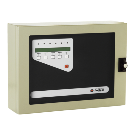
Page 6: Led Indicators
4 CONTROL UNIT CUE Rev. A MC Date: 030224 ED INDICATORS Mode indicator Green LED ON – normal operation. Green LED FLASHING – Control unit in test mode. Green LED OFF – power failure. Malfunction indicator Red LED normally OFF. -
Page 7: Text Messages
Solve the problem in a suitable way. Replace the fuses. INT. POWER ERROR Cause: Internal voltage is faulty Trouble-Shooting: Check that no cables are disconnected or that something may have caused a short-circuit. Action: Solve the problem or contact Firefly AB. - Page 8 6 CONTROL UNIT CUE Rev. A MC Date: 030224 BAT. POWER ERROR Cause: Broken electrical circuit or faulty battery. Trouble-Shooting Check that the battery cables are connected and that the batteries are functioning. Action: Connect the battery cables. Replace the faulty battery with a new one.
- Page 9 7 CONTROL UNIT CUE Rev. A MC Date: 030224 DETECTOR X SENSITIV Cause: Sensitivity of the detector connected to input D1 is not Corresponding to the configuration in the control unit. Trouble-Shooting: Check in the project documentation which sensitivity the Detector should have.
- Page 10 Action: Rectify the error. UNKNOWN UNKNOWN Cause: Incorrect main program. Trouble-Shooting: Contact FIREFLY AB. Action: According to FIREFLY AB’s instructions. (Flashing) SYSTEM RESTART Cause: Incorrect master program or faulty processor. Trouble-Shooting: Contact FIREFLY AB. Action: According to FIREFLY AB’s instructions.
-
Page 11: Activity Messages
CGF- RISC Cause: Incorrect program file in the configuration program. Trouble-Shooting: Contact FIREFLY AB. Action: According to FIREFLY AB's instructions. *ACTIVITY MESSAGES EXPLOSIVE X ACTIVE Cause: Explosive output 1 has been activated. Action: Reset the alarm with key for "reset". -
Page 12: Menus
10 CONTROL UNIT CUE Rev. A MC Date: 030224 ENUS The control units has 6 keys to operate the unit. Five are located under the display. This are as follows: All functions keys are menu controlled. The function for each key is displayed above respective key. The sixth key is used to reset audible and visual alarms. -
Page 13: Menu Selection: Set Date And Time
11 CONTROL UNIT CUE Rev. A MC Date: 030224 Step backwards or forwards by pressing “PREV.” or “NEXT”. To finish press “ABORT” and the display will return to show the current information. If none of the keys has been pressed within 60 seconds, the display will automatically return to show the current status of the system. -
Page 14: Menu Selection: Change System State
12 CONTROL UNIT CUE Rev. A MC Date: 030224 MENU SELECTION: CHANGE SYSTEM STATE Purpose: To change system state for the control unit. The display will show the current status of the system. Date Time ? ? ? ? ? ? ? ? ? ? ? -
Page 15: Menu Selection: Select Language
13 CONTROL UNIT CUE Rev. A MC Date: 030224 MENU SELECTION: SELECT LANGUAGE Purpose: To select operating language for the central unit. The display shows the current status of the system. Date Time ? ? ? ? ? ? ? ? ? ? ? - Page 16 14 CONTROL UNIT CUE Rev. A MC Date: 030224 AVAILABLE MENUS DRIVEN BY EVENTS - DISPLAY ERROR LIST The hidden menus will be available to - DISPLAY ERROR LIST the operator when necessary due to system - RESET PROCESS STOP configuration.
- Page 17 15 CONTROL UNIT CUE Rev. A MC Date: 030224 MENU SELECTION: RESET PROCESS STOP Purpose: To reset the system after a process stop. The display shows the current status of the system. Date Time ? ? ? ? ? ? ? ? ? ? ?
- Page 18 16 CONTROL UNIT CUE Rev. A MC Date: 030224 MENU SELECTION: EXPLOSIVE OUTPUTS Purpose: To switch the explosive outputs ON or OFF. Note: When a explosive output has been activated it will automatically be switched off. This means that the system can be left in a running position after an explosive output has been activated.
- Page 19 17 CONTROL UNIT CUE Rev. A MC Date: 030224 6. The display shows: Blocking time in seconds Blocking time in seconds EXPL. 1 0000 EXPL . 2 0000 ? ? ? ? 1-OFF 2-OFF ABORT ENTER Press “ENTER”. The display will show.
- Page 20 18 CONTROL UNIT CUE Rev. A MC Date: 030224 MENU SELECTION: RESET OUTPUTS Purpose: To manually reset outputs that have been programmed for manually reset. This menu can in some cases be delayed by the countdown time from the process stop.
- Page 21 19 CONTROL UNIT CUE Rev. A MC Date: 030224 MENU SELECTION: FLOW SENSOR CALIB. Purpose: To calibrate the flow measurement. The display shows the current status of the system. Date Time ? ? ? ? ? ? ? ? ? ? ?
-
Page 22: Layout
20 CONTROL UNIT CUE Rev. A MC Date: 030224 AYOUT MAIN CARD TERMINALS / COMPONENTS Terminal block T1: Data communication IN/OUT. Terminal block T2-T5: Inputs for max. 8 detectors. Terminal block T6: Inputs for 4 external sensors. Terminal block T7-T8: Outputs for max. -
Page 23: Technical Data
21 CONTROL UNIT CUE Rev. A MC Date: 030224 POWER SUPPLY CARD TERMINALS Terminal block T0: Incoming supply 230/115 AC ±20%. VOLTAGE SELECTOR : 110/220 V AC FUSES : … A fuses SW1: Main supply switch. ECHNICAL DATA Voltage supply: 115/230 VAC ±20%. - Page 24 22 CONTROL UNIT CUE Rev. A MC Date: 030224 Complies with EMC standards (emission): EN 50 081-1 (1992). Complies with EMC standards (immunity): EN 50 081-2 (1995). ENV 50 142 (1994). Solenoid valves outputs: 8 pcs. 24 VDC. Max 0,5 A.
Need help?
Do you have a question about the CUE and is the answer not in the manual?
Questions and answers