Table of Contents
Advertisement
Available languages
Available languages
Installation, Operation & Maintenance
Instructions for MF Series Solution Feeders
Startup Procedure
1) Close isolation valve between feeder and system
connection point
2) Fill reservoir, turn valve on feeder to mix/purge and
plug in
3) Ensure pump is cycling fluid through reservoir (primed)
4) Turn valve to run and open isolation valve to system
2615 Wentz Avenue, Saskatoon, SK S7K 5J1 Ph: (306) 651-1815 Fax: (306) 651-2293
email: sales@axiomind.com website: www.axiomind.com
INDUSTRIES LIMITED
En Français Page 12
Advertisement
Table of Contents

Summary of Contents for Axiom MF Series
- Page 1 INDUSTRIES LIMITED Installation, Operation & Maintenance Instructions for MF Series Solution Feeders En Français Page 12 Startup Procedure 1) Close isolation valve between feeder and system connection point 2) Fill reservoir, turn valve on feeder to mix/purge and plug in...
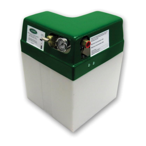
- Page 2 INDUSTRIES LIMITED MF200 and MF300 HYDRONIC SYSTEM FEEDER INSTALLATION, OPERATION AND MAINTENANCE INSTRUCTIONS The System Feeder is used to maintain a minimum system pressure within a hydronic heating or cooling system. It should be used to pressurize the system while system temperature is at it’s lowest.
- Page 3 COLD STATIC FILL PRESSURE The cold static fill pressure (CSFP) in a closed hydronic system has to be high enough to accomplish three things. 1) Overcome the static head (height) between the fill point and the highest point in the system. 2) Provide adequate pressure (minimum 4 psig) at the top of the system for proper air venting.
- Page 4 Purger Pump Expansion Tank MF 200 Connection Schematic – MF 200 Packaged System Feeder...
- Page 5 Connecting the Alarm Contacts in the MF Series to Other Alarm Systems The alarm switch contacts in the MF series are factory wired to be OPEN on LOW PRESSURE. The switch is SPDT, so if some other alarm system is connected to this alarm contact and can not be configured to work with an open contact, the wiring on the low-pressure micro-switch can be changed to provide a closed contact on low pressure.
- Page 6 MF200-1420 power adapter bracket MF200-0500 tank bung MF200-0110 side decal s/n decal MF200-1100 MF200-0970 5/8" plastic clamp MF200-0980 ¼” check valve PROJECT MF-200 (EXPLODE) AXIOM INDUSTRIES CUSTOMER DRWG. NO. EQUIP. NO. JOB NO. DATE TLL-MF200-1005 13 OCTOBER 2005 PARTS LIST...
- Page 7 MF200-1420 MF200-0500 tank bung MF200-0110 side decal s/n decal MF200-1100 MF200-0970 5/8" plastic clamp MF200-0980 ¼” check valve PROJECT MF-300 (EXPLODE) AXIOM INDUSTRIES CUSTOMER DRWG. NO. EQUIP. NO. JOB NO. DATE TLL-MF300-1005 13 OCTOBER 2005 PARTS LIST...
- Page 8 Installation Instructions for the RIA10-1-SAA Control Panel for use with MF200 & MF300 Feeders The MF series alarm dry contacts are factory wired to provide an OPEN contact on LOW PRESSURE. This is compatible with the alarm circuit in the RIA10-1-SAA panel. Connect terminals 1 and 2 from terminal block TB2 in the panel to the contact terminals located beside the power plug on the MF unit.
- Page 10 Troubleshooting Chart Symptom Possible Cause Resolution Fluid level in tank is low Add correct fluid. Check for cause Pump will not start of system fluid loss Blown fuse Check LED indicator light on power cord, check fuse and replace if needed (2.5 Amps) Power supply or Breaker Check LED indicator light on power...
- Page 11 Noisy / Rough operation Pump is overloaded and pump Obtain Replacement pump from pressure switch not cutting out reseller and install Loose pump head or drive screws Tighten screws Feeder is plumbed with rigid pipe Plumb with PEX or plastic pipe causing noise to transmit Feeder Leaking Manifold block over tightened and...
- Page 12 Pump Cycles Continually Air is being removed from system No action required and pump is only making up fluid Leak in system Inspect system and repair leak Check valve or Regulator installed Remove check valve or regulator between System Feeder and system...
- Page 13 INDUSTRIES LTÉE INDUSTRIES LTÉE Alimentateurs de solution MF Instructions d’installation, de fonctionnement et d’entretien Procédure de mise en marche 1. Fermer le robinet d’isolement entre l’alimentateur et le raccordement au système. 2. Remplir le réservoir, tourner la manette du robinet à Mélange (Mix) sur l’alimentateur et brancher.
- Page 14 Alimentateurs de solution MF Instructions d’installation, de fonctionnement et d’entretien Le MF200 est utilisé pour maintenir une pression minimum du système dans un système de chauffage ou de refroidissement hydronique. Il devrait être utilisé pour pressuriser le système quand la température du système est au plus bas. Installation 1.
- Page 15 PRESSION DE REMPLISSAGE STATIQUE À FROID La pression de remplissage statique à froid dans un système hydronique en circuit fermé doit être suffisamment élevée pour accomplir trois choses. 1) surmonter la charge statique (la hauteur) entre le point de remplissage et le point le plus élevé dans le système.
- Page 16 Séparateur d’air et purgeur Pump Réservoir d’expansion MF 200 Schéma de raccordement – Ensemble d'alimentation MF...
- Page 17 Mode d’installation du panneau de contrôle RIA10-1-SAA à utiliser avec les alimentateurs MF200 & MF300 Les contacts secs de l’alarme de la série MF sont réglés à l’usine pour fournir un contact OUVERT à BASSE PRESSION. C’est compatible avec le circuit d’alarme dans le panneau RIA10-1-SAA.
- Page 19 MF200-1420 power adapter bracket MF200-0500 tank bung MF200-0110 side decal s/n decal MF200-1100 MF200-0970 5/8" plastic clamp MF200-0980 ¼” check valve PROJECT MF-200 (EXPLODE) AXIOM INDUSTRIES CUSTOMER DRWG. NO. EQUIP. NO. JOB NO. DATE TLL-MF200-1005 13 OCTOBER 2005 PARTS LIST...
- Page 20 MF200-1420 MF200-0500 tank bung MF200-0110 side decal s/n decal MF200-1100 MF200-0970 5/8" plastic clamp MF200-0980 ¼” check valve PROJECT MF-300 (EXPLODE) AXIOM INDUSTRIES CUSTOMER DRWG. NO. EQUIP. NO. JOB NO. DATE TLL-MF300-1005 13 OCTOBER 2005 PARTS LIST...
- Page 21 Troubleshooting Chart Problème Cause possible Mesure corrective La pompe ne démarre pas Niveau de solution trop bas dans Ajouter la quantité de liquide le réservoir nécessaire. Rechercher la cause de fuite dans le système. Fusible grillé Vérifier le témoin DEL sur le cordon d'alimentation.
- Page 22 Une fuite du tube d'aspiration fait Remplacer le tube et réparer la entrer de l'air fuite. Débit trop restreint du tube Remplacer le tube. d'aspiration ou de refoulement (pincé) Fonctionnement bruyant Pompe surchargée et pressostat Remplacer la pompe. de pompe inopérant Vis de tête de pompe ou Resserrer les vis.
- Page 23 Pression du système trop Pressostat réglé à un point de Régler le pressostat selon les consigne inapproprié directives du manuel d’entretien. élevée L’amortisseur du pressostat est Remplacer l’amortisseur. Voir à ce bouché que la solution soit propre. Pressostat défectueux Remplacer l’amortisseur et le pressostat.
Need help?
Do you have a question about the MF Series and is the answer not in the manual?
Questions and answers