
Related Manuals for CHINT NRE8 Series


Summary of Contents for CHINT NRE8 Series
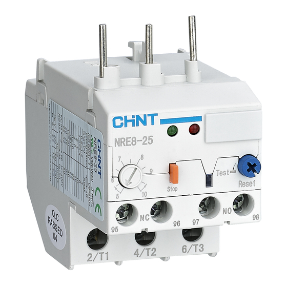
- Page 1 NO:2020.04 NRE8 Series Electronic Overload Relay User Instruction Standard: IEC/EN 60947-4-1...
-
Page 2: Safety Warning
Safety Warning Only professional technicians are allowed for installation and maintenance. Installation in any damp, condensed-phase environment with inflammable and explosive gas is forbidden. When the product is being installed or maintained, the power must be switched off. You are prohibited from touching the conductive part when the product is operating. - Page 3 Use Purpose NRE8 electronic overload relay (hereinafter referred to as relay) is applicable to circuits with frequency of AC 50Hz or 60Hz, rated operating voltage up to 690V and current from 0.6 to 100A. It is used for overload protection and phase-failure protection of long-term operating or intermittent operating AC motor.
- Page 4 Frame size Rated Adjustment Fuse Model rated current range of setting gG Amax current A current A NRE8-25 22~32 0.6~1.2 1.2~2.4 NRE8-38 5~10 7~12 10~20 19~38 5~10 NRE8-40 10~20 20~40 30~65 NRE8-100 50~100 Table 2 Technical parameters of auxiliary circuit AC-15 DC-13 Application category...
- Page 5 Table 3 Technical parameters and performance Content Parameters AC690 Rated insulation voltage of main circuit Ui(V) AC400 Rated insulation voltage of auxiliary circuit Ui(V) 50/60Hz Rated frequency (Hz) Rated duty system, specify intermittent duty 8 hour duty system or level (if any) uninterrupted duty system Rated impulse withstand voltage Uimp (kV) IP20...
- Page 6 t(s) 1000 I/Ie 1---Cold state 2---Thermal state Figure 1 Relay time - current characteristic curve...
-
Page 7: Installation
Installation 1) Installation Unit: mm 26.3/27.6 81.5max 61.5 NRE8-25 Test Stop Reset 6 T3 2 T1 4 T2 46max Figure 2 Overall and installation dimensions of NRE8-25 45max Unit: mm 91max 35.5 1 L1 3 L2 NRE8-25 Test Stop Reset 4 T2 6 T2 Figure 3 Overall and installation dimensions of NRE8-25/F... - Page 8 Unit: mm 5max 14.5±0.5 14.5±0.5 47.3±0.3 46max Figure 4 Overall and installation dimensions of NRE8-38 Unit: mm 93max NRE8-40 Test Reset Stop 6 T3 2 T1 55max Figure 5 Overall and installation dimensions of NRE8-40...
- Page 9 Unit: mm 55max 104max NRE8-40 Test Reset Stop 4 T2 Figure 6 Overall and installation dimensions of NRE8-40/F (with mounting bracket) Unit: mm 101max 20/23.5 20/23.5 74.6 NRE8-100 Test Reset Stop 96 97 2 T1 4 T2 6 T3 Figure 7 Overall and installation dimensions of NRE8-100...
- Page 10 Unit: mm 72max 61.5 118max Figure 8 Overall and installation dimensions of NRE8-100/F (with mounting bracket) Table 5 Wiring capacity of terminals M3.5 NRE8 0.75~2.5 0.75~2.5 0.75~2.5 0.75~2.5 0.75~2.5 0.75~2.5 Series A>3.5mm, 1.2 N.m L<8mm NRE8-25 NRE8-38 1~10 1~10 1~10 1~10 1~10 1~10 A>3mm, 1.7 N.m L<10mm...
- Page 11 2) Operation and commissioning Circuit working status Indicator status Green light flashing, red light off Normal Green light flashing, red light on Overload delay Green light on, red light flashing Phase-failure delay Green light light Mannal reset function Continuously adjustable current range T est funcion Emergency...
-
Page 12: Maintenance
Maintenance Clean the dust on the electronic overload relay timely. Conduct product test and maintenance every half a year to ensure the smooth operation of the product and the good contact of NO and NC contacts. Tighten the terminal screws with specified torque and align the load protection capability of the electronic overload relay according to commissioning requirements. -
Page 13: Environmental Protection
Table 6 Analysis and Troubleshooting of Faults Symptoms Cause analysis Troubleshooting method and precautions Change to product with bigger size. Size is too small. The set current value is Misoperation smaller than the actual Fine tune the cam clockwise so that the set of thermal operating current of the current matches the actual motor current. - Page 14 QC PASS NRE8 Series Electronic Overload Relay IEC/EN 60947-4-1 Check 24 Test date: Please see the packing ZHEJIANG CHINT ELECTRICS CO.,LTD.
- Page 15 NRE8 Series Electronic Overload Relay User Instruction Zhejiang Chint Electrics Co., Ltd. Add: No.1, CHINT Road, CHINT Industrial Zone,North Baixiang, Yueqing, Zhejiang 325603,P.R.China E-mail: global-sales@chint.com Website: http://en.chint.com...
Need help?
Do you have a question about the NRE8 Series and is the answer not in the manual?
Questions and answers