
Related Manuals for Igema FARB2


Summary of Contents for Igema FARB2
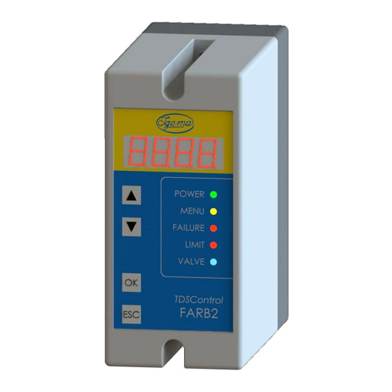
- Page 1 TDS Controller with limiting function FARB2 for use with the TDS probe: EL18, EL22 or EL23 Edition 04/2021 D-08-B-52502-EN-01 INSTALLATION- AND OPERATING INSTRUCTION...
- Page 2 Product philosophy Thank you for placing your trust in IGEMA and deciding in favour of one of our high-quality products. For more than 100 years, measuring and control systems have been developed, produced and sold worldwide under the IGEMA brand name.
-
Page 3: Table Of Contents
3. Principle picture ....................10 4. System description ................... 10 4.1 Application ...................... 10 4.2 Function ......................11 5. Design and installation FARB2 ................ 12 5.1 Installation dimensions and descriptions ............12 5.2 Installation ....................... 13 5.3 Electrical connection ..................13 5.3.1 Wiring diagram 110 –... - Page 4 Table of contents 7. Configuration via menu ..................20 7.1 Basics ......................20 7.2 Diagram ......................20 7.3 Description ...................... 21 7.3.1 Note ......................21 7.3.2 Function of the menu items ................. 21 7.4 Programming ....................22 7.4.1 Password input ................... 22 7.4.2 Input of functionality of the change-over-contact: limiter or controller ..
- Page 5 Table of contents 11. Technical Data ....................26 11.1 Device data - Controller ................26 11.2 Device data - Contacts ................26 11.3 Rating Plate ....................27 12. LED-Display ....................... 28 13. Fault analysis ....................29 14. Declaration of Conformity ................30...
-
Page 6: Important Safety Instructions
Unqualified persons must not be assigned the above tasks! IGEMA GmbH accepts no liability for damage to property or personal injury caused by unqualified persons or by failure to observe these installation and operating instructions. If no sufficiently qualified person can be found, IGEMA GmbH can be commissioned with the installation/maintenance. -
Page 7: Intended Use Of The Device
The correct installation position, alignment and flow direction of the device must be observed! Before installing the IGEMA product on boilers or containers, it is essential to remove all protective covers and, if necessary, the protective film from rating plates and sight glasses. -
Page 8: Safety At Work
1.3 Safety at work Before installation or carrying out maintenance work on the device, safe access must be ensured and a secure working area with sufficient lighting must be defined and marked out. Always use lifting equipment for heavy loads! Danger Before starting any work, carefully check which liquids or gases are or have been in the pipeline. -
Page 9: Safety Instructions For This Device
IGEMA GmbH Mess- und Regelsysteme will assume no liability if the above regulations, instructions and safety precautions are not observed and followed. If they are not expressly listed in the installation and operating instructions, changes to an IGEMA device are carried out at the risk of the user. -
Page 10: Principle Picture
- Motor control open/close System description 4.1 Application The TDS controller with limiting function FARB2 is used for continuous monitoring of the conductivity of liquids. The conductivity is measured with a measuring cell. This consists of a special conductivity probe and the container wall or protective tube. -
Page 11: Function
Info The connection of the relay output defines the function of the unit: If the output is integrated in a switch-off / safety circuit, the functionality of FARB2 is based on the limiting function. The relay output is active (contacts 3-4 closed) during normal operating condition. -
Page 12: Design And Installation Farb2
The TDS Controller with limiting function, FARB2, is used for monitoring the TDS as stated in EN 12953-6. The TDS of the boiler water has to be monitored continuously to ensure that the TDS stays within the given limits. Info The relevant standard for safety accessories, EN 12953-9, does not give specific requirements for TDS limiters. -
Page 13: Installation
5.2 Installation Ensure protection class in accordance with local regulations Caution electrical voltage With top-hat DIN rail mounting for standard DIN46277 35 mm carrier rail: • Snap the device on the standard carrier rail. • Loosen the fastening screws and remove the hood from the base. •... -
Page 14: Wiring Diagram 110 - 240 V Ac
5.3.1 Wiring diagram 110 – 240 V AC Back plate Probe plug user site Electrode rod ● e.g.: Valve, PLC, FARB2 industrial controller Auxiliary voltage Signal output... -
Page 15: Wiring Diagram 24 V Dc
5.3.2 Wiring diagram 24 V DC Back plate Probe plug user site Electrode rod ● e.g.: Valve, PLC, FARB2 industrial controller Auxiliary Voltage Signal output The negative connection of the supply is connected to PE via the probe ground! Caution... -
Page 16: Procedure
• Use a shielded cable for the current output. • Only connect shielding on the FARB2 control unit (terminal 12). • After connecting to the power supply – with the device disconnected – place the hood on the base and tighten the fastening screws. - Page 17 Fitting the TDS probe It is essential to remove the cardboard protective tube for transport before installation!! Caution If several probes are screwed into one flange, the probe plug and the associated probe should be labelled to prevent confusion! Info Screw connection of the TDS probe •...
- Page 18 6.1 EL22 This TDS probe is usually fitted horizontally into the boiler using a T-piece. This enables the concentrated water, which is measured, to be directly discharged. In order to determine the length, note that there should be a free space of 40mm around the measuring tip.
- Page 19 6.2 EL23 This TDS probe is usually fitted horizontal to vertical using a protective tube. 6.3 EL18 This TDS probe is usually fitted using a flange in a pipe. With intermittent flow, a measurement can then be carried out and TDS reduction can be started. Installation position: horizontal to vertical.
-
Page 20: Configuration Via Menu
7. Configuration via menu 7.1 Basics The menu of the FARB2 is divided into two main levels: Main level 1 | Main level 2 “OK” The menu is brought up by pressing the key. While the operator is in the configuration menu, the associated yellow LED flashes or lights up. -
Page 21: Description
Factory setting 0025 2.4: Enter the conductivity of the medium; for determination see chapter 8 2.5: Perform calibration! FARB2 connected with probe Probe in medium 2.6: Adjustment of lower switching point / return to operating state 0µS ... xxxxµS / upper switching point must be smaller than the upper switching point (2.6) -
Page 22: Programming
7.4 Programming The prerequisite for programming is an operational system FARB2 / EL22/23/18. The probe must be installed and connected. The system must be at operating temperature. Caution 7.4.1 Password input In menu item 2.1., a "0. 0 0 0"... -
Page 23: Perform Calibration
7.4.5 Perform calibration In menu item 2.5. the display shows "CALI" after you confirm with "OK". Press the "OK" key again to calculate the entered values from 2.3 and 2.4 together with the current measured value. The display shows "ok". Press the "OK"... -
Page 24: Programming The Conductivity Value For 20Ma Current Output
The other values are programmed in the same way. In this way any number of measuring ranges can be realised. IGEMA recommends, depending on the system parameters, the ranges: 100µS/cm, 1.000µS/cm und 10.000µS/cm. Over the entire measuring range, the typical measuring deviation around the calibration point is +-2% of the measuring range end value. -
Page 25: Initial Operation
8. Initial operation When the FARB2 is used for the first time, not all the data required for operation are yet available in the device. The FARB2 indicates this with "Set ". Settings must now be made (see also chapter 9): Operating mode: •... -
Page 26: Switching Value Settings
10. Switching value settings Standards 12953-10 and 12952-12 specify requirements for boiler water and feed water according to the permissible operating overpressure. Caution limiter: The limit value must be defined and set (menu 2.7). The value for the return to normal operating mode must be defined and set (menu 2.6) The relay is actively energised in normal operating mode (contacts 3-4 closed). -
Page 27: Rating Plate
11.2 Rating Plate FARB2 100-240V AC 24V DC 20-10031 24V DC 3,0 W 212010031000 EL18 EL23 EL22... -
Page 28: Led-Display
12. LED-Display Display Description State-1 State-2 Error-free Permanent green Basic status operation Supply low limit Flashing green Basic status LED (1Hz) < 180V Current operating Permanent yellow Device ready for programming conditions Relay de-energised Permanent red Current output: Device faulty <2,1mA Relay de-energised, Permanent red... -
Page 29: Fault Analysis
Display „OPEn“ Current output 3,5mA This high-quality IGEMA product was designed, manufactured and tested with the application of the QM System guidelines in accordance with DIN EN ISO 9001:2015. If the device supplied indicates transport damage or gives cause for complaint in spite of our final quality control please contact our SERVICE department on telephone +49 2501 92424-0 by return. -
Page 30: Declaration Of Conformity
14. Declaration of Conformity... - Page 32 IGEMA GmbH Antwerpener Str. 1 Fon.: +49 2501 92424-0 48163 Münster Fax.: +49 2501 92424-99 Deutschland info@igema.com www.igema.com...
Need help?
Do you have a question about the FARB2 and is the answer not in the manual?
Questions and answers