
Summary of Contents for Hiltron security PCM20
- Page 1 PCM20 Centrale di automazione a 230V per cancello ad ante MANUALE PER L'UTENTE...
- Page 2 PCM20 - Manuale per l'utente security Norme generali per la sicurezza Leggere attentamente le istruzioni prima di iniziare I'installazione del prodotto e conservarle per riferimenti futuri. Installazione, collegamenti elettrici e regolazioni devono essere effettuati nell'osservanza delle norme di buona tecnica e di sicurezza vigenti (UNI 8612).
-
Page 3: Table Of Contents
Introduzione security Indice Introduzione Capitolo 1 1.1 Descrizione della scheda ..................4 1.2 Caratteristiche funzionali...................4 1.3 Caratteristiche tecniche..................4 Installazione Capitolo 2 2.1 Descrizione della scheda ..................5 2.2 Esempio d'installazione dell’impianto..............6 2.3 Descrizione della morsettiera................7 2.4 Collegamenti .....................8 2.4.1 Rete di alimentazione, lampeggiatore e motoriduttori ......8 2.4.2 Fotocellule .....................9 2.4.3 LED di segnalazione, comandi ed elettroserratura ......10 2.4.4 Decoder DEC20 con antenna BIRD.............11... -
Page 4: Introduzione
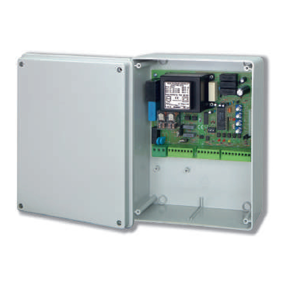
. Descrizione della centrale La PCM20 è una centrale di automazione per cancelli ad ante. Essa gestisce due motoriduttori a 230Vca 700VA max ognuno, tipo MB3DX (per anta destra) ed MB3SX (per anta sinistra) prodotti dalla HILTRON. La gestione avviene tramite frizione elettronica, realizzata con un microprocessore di nuova generazione. -
Page 5: Installazione
Installazione security Installazione Descrizione della scheda Fusibile rete JP2 / JP3 Esclusione canale B Fusibile periferiche LED 5 Controllo impulso A Fusibile elettroserratura LED 4 Controllo impulso B Fusibile logica LED 3 Controllo impulso STOP Reg. sfasamento ante LED 2 Stato fotocellula apertura Reg. -
Page 6: Esempio D'installazione Dell'impianto
PCM20 - Manuale per l'utente security Esempio d'installazione dell’impianto PCM20 Centrale per automazione FX55 (TX) Fotocellule trasmittenti di chiusura FX55 (RX) Fotocellule riceventi di chiusura LAMP / PULSAR Lampeggiatore 230V BIRD Antenna con ricevitore VHF Elettroserratura PM4230 (SX) Motoriduttore sinistro (2) -
Page 7: Descrizione Della Morsettiera
Installazione security Descrizione della morsettiera 1 - Fase 2 - Terra ± RETE DI ALIMENTAZIONE 230V~ 10% 50Hz 3 - Neutro 4 - Polo 1 LAMPEGGIATORE 230V~ 5 - Polo 2 6 - apertura MOTORIDUTTORE 1 7 - comune 230V~ 700W max 8 - chiusura 9 - apertura MOTORIDUTTORE 2... -
Page 8: Collegamenti
PCM20 - Manuale per l'utente security Collegamenti 2.4.1 Rete di alimentazione, lampeggiatore e motoriduttori 3x1,5mm 3x1,5mm LAMP / PULSAR ( Lampeggiatore 230V~ MOTORIDUTTORE 1* ( MOTORIDUTTORE 2 ( 230V~ 700W max 230V~ 700W max 3x1,5mm RETE DI ALIMENTAZIONE 230V~ ±10% 50Hz... -
Page 9: Fotocellule
Installazione security 2.4.2 Fotocellule 24V~ 24V~ FX55 ( FX55 ( 24V~ 24V~ FX55 ( FX55 ( 24V~ 24V~ FX55 ( FX55 ( 24V~ 24V~ FX55 ( FX55 ( Opzionali. Ponticellare Com. - Op. se non sono installate tali fotocellule. -
Page 10: Led Di Segnalazione, Comandi Ed Elettroserratura
PCM20 - Manuale per l'utente security 2.4.3 LED di segnalazione, comandi, elettroserratura LED di segnalazione stato cancello Apertura parziale Apertura totale Pulsanti di comando opzionali tramite relè (da citofono, etc.) STOP APRE CHIUDE SC1 ( 12V~ Elettroserratura NOTA : Nel caso in cui il motore non fosse collegato alla centrale ( se non c'è un carico ) non è possibile... -
Page 11: Decoder Dec20 Con Antenna Bird
Installazione security 2.4.4 Decoder DEC20 con antenna BIRD DEC20 Jumpers JP2 - JP3 Canale B Entrambe ON Entrambe OFF OFF* * In tal caso è disattivato il comando di apertura parziale del cancello. BIRD ATTENZIONE: utilizzare un cavo schermato a due conduttori, tipo 2S, dedicato al collegamento del solo ricevitore BIRD. -
Page 12: Programmazione
PCM20 - Manuale per l'utente security Programmazione Logica di funzionamento La centrale PCM20 può funzionare secondo due diverse logiche di funzionamento, descritte dettagliatamente nel capitolo 4 “Funzionamento”; esse sono adattabili alle diverse esigenze dell’utente: " Funzionamento automatico " Funzionamento passo/passo con STOP E’... -
Page 13: Esclusione Del Secondo Motoriduttore
Funzionamento security Esclusione del secondo motoriduttore E’ possibile disattivare il controllo del motore 2 nel caso in cui la centrale PCM20 sia destinata ad automatizzare un cancello ad anta singola. Tale impostazione è determinata dal jumper JP1: JP1 ON (default) Controllo dei due motoriduttori. -
Page 14: Funzionamento
PCM20 - Manuale per l'utente security Funzionamento LEDs di controllo Sono presenti cinque LEDs sul circuito per facilitare il controllo del funzionamento delle apparecchiature periferiche e degli impulsi di comando: LED 1 rosso Controllo stato delle fotocellule di chiusura LED 2... -
Page 15: Logiche Di Funzionamento
Manutenzione security Logiche di funzionamento 4.2.1 Funzionamento AUTOMATICO IMPULSI DI COMANDO IMPEGNO IMPEGNO STATO DEL IMPULSO IMPULSO A IMPULSO B FOTOCELLULA FOTOCELLULA CANCELLO STOP DI CHIUSURA DI APERTURA Apre le ante e le richiude CHIUSO Nessun effetto dopo il tempo di pausa Resta in pausa fino APERTO IN Richiude immediatamente... -
Page 16: Manutenzione
PCM20 - Manuale per l'utente security Manutenzione Cancello Eseguire controlli periodici della struttura del cancello ed in particolare verificare la perfetta condizione delle cerniere e delle altre parti meccaniche soggette ad usura. Fusibili 5A 250V Fusibile RETE Questo fusibile protegge contro eventuali... - Page 17 PCM20 230V automation central unit for winging gate USER MANUAL...
- Page 18 PCM20 - User Manual security Important Safeguards Please read this manual carefully before the installation and keep it for future reference. Installation, electrical connections and adjustements must comply with technical and safety standards in force. (UNI 8612). HILTRON Srl cannot be held responsible for failure to observe technical standards in the construction of gates, or for any deformation of gates which may occur during the use.
- Page 19 Introduction security Index Introduction Chapter 1 1.1 Central Unit Description ..................20 1.2 Central Unit Overview ..................20 1.3 Technical Features ..................20 Installation Capitolo 2 2.1 Board Description....................21 2.2 Example of installation ..................22 2.3 Terminal Board Description ................23 2.4 Connections ....................24 2.4.1 Power supply, Flasher and Geared-motors .........24 2.4.2 Photocells ....................25 2.4.3 Check LEDs, Controls and Electric Lock ..........26 2.4.4 DEC20 Decoder with BIRD antenna ...........27...
- Page 20 HILTRON, by an electrical clutch, realized with a microprocessor of last generation. PCM20 is furnished with a sophisticated circuit of elctronical check that checks constantly the proper operating of the system and of connected devices; in case of troubles this circuit stops all central unit operations.
- Page 21 Installation security Installation Board Description Voltage Fuse JP2 / JP3 B channel exclusion Peripheral Fuse LED 5 Pulse A check Electric lock Fuse LED 4 Pulse B check Operating modes Fuse LED 3 STOP Pulse check Wing Phase Difference Adj. LED 2 Opening Photocell status Opening/Closing Time adj.
- Page 22 PCM20 - User Manual security Example of installation PCM20 Central Unit FX55 (TX) TX Closing Photocellsa FX55 (RX) RX Closing Photocells LAMP / PULSAR 230V Flasher BIRD Antenna con ricevitore VHF Electric Lock PM4230 (SX) Left Geared-motor (2) PM4230 (DX)
- Page 23 Installation security Terminal Board Description 1 - phase 2 - ground ± POWER SUPPLY 230V~ 10% 50Hz 3 - neutral 4 - pole 1 FLASHER 230V~ 5 - pole 2 6 - opening GEARED-MOTOR 1 7 - common 230V~ 700W max 8 - closing 9 - opening GEARED-MOTOR 2...
- Page 24 PCM20 - User Manual security Connections 2.4.1 Power supply, flasher and geared-motor 3x1,5mm 3x1,5mm LAMP / PULSAR ( Flasher 230V~ GEARED-MOTOR 1* ( GEARED-MOTOR 2 ( 230V~ 700W max 230V~ 700W max 3x1,5mm POWER SUPPLY 230V~ ±10% 50Hz The geared-motor 1 is installed on the wing that is the first to open and that has the electric lock...
- Page 25 Installation security 2.4.2 Photocells 24V~ 24V~ FX55 ( FX55 ( 24V~ 24V~ FX55 ( FX55 ( 24V~ 24V~ FX55 ( FX55 ( 24V~ 24V~ FX55 ( FX55 ( Optionals. If these photocells aren’t installed, you must jump Com. - Op.
- Page 26 PCM20 - User Manual security 2.4.3 Check LEDs, controls, electric lock Check LED gate status Partial opening Total opening Optional Controls buttons by relay (entry phone, etc.) STOP OPEN CLOSE SC1 ( 12V~ Electric Lock NOTE : In the case in which the motor she was not connected to they centers (if not there is a cargo) is...
- Page 27 Installation security 2.4.4 Decoder DEC20 with antenna BIRD DEC20 Jumpers JP2 - JP3 Channel B Both of them ON Both of them OFF OFF* * In this case, partial opening control is disabled. BIRD WARNING: Use a shielded cable with two wires, 2S type, only for the connection of BIRD receiver Do not use free wire of another devices.
- Page 28 PCM20 - User Manual security Programming Operating Modes PCM20 Central Unit can work in two different operating modes programmable by the user, as described in the chapter 4 “Operating Procedures”: " Automatic Operating " Step-by-step with STOP Operating It’s possible to set the operating mode by the micro-switch 1 of dip-switch SW1 (see table 1).
- Page 29 Programming security Exclusion of geared-motor 2 It’s possible to disactivate the geared-motor 2, in case of PCM20 central unit must automatize one wing gate. This setting is controlled by the jumper JP1: JP1 ON (default) Two geared-motors. JP1 OFF Only geared-motor 1.
- Page 30 PCM20 - User Manual security Operating Check LEDs There are 5 LEDs on the board to make easy the check of peripheral devices and control pulses operating: LED 1 Closing Photocells status check LED 2 Opening Photocells status check LED 3...
- Page 31 Operating security Operating Modes 4.2.1 AUTOMATIC mode PULSES GATE STOP CLOSING OPENING PULSE A PULSE B STATUS PULSE PHOTOCELL PHOTOCELL Opens the wings and reclosed CLOSED No action them after the time of pause Closes the wings OPEN IN The operating procedure will be in pause up to have liberated the passing immediately PAUSE...
- Page 32 PCM20 - User Manual security Maintenance Gate It’s suggested to carry out periodic checks on the structure of the gate and in particular to verify the perfect condition of hinges and of all mechanical elements. Fuses 5A 250V VOLTAGE Fuse...
Need help?
Do you have a question about the PCM20 and is the answer not in the manual?
Questions and answers