
Summary of Contents for Resodyn LabRAM ResonantAcoustic
- Page 1 ResonantAcoustic® Mixer User Manual Including Vacuum System Assembly and Operation Resodyn Acoustic Mixers, Inc. 130 N. Main Street, Suite 630 Butte, MT 59701 (406) 497-5333 www.resodynmixers.com Doc. No. 100338B...
-
Page 2: Table Of Contents
LabRAM Users Manual – Revised 3/18/11 TABLE OF CONTENTS TABLE OF CONTENTS SAFETY INSTRUCTIONS Types of Notices ....................3 General Safety Guidelines .................. 3 DEFINITIONS INTRODUCTION TO THE LabRAM MAJOR COMPONENTS Overall Assembly ....................6 Resonator ......................7 Power Supply and Control .................. 9 Standard Vessel Fixture and Vessels .............. -
Page 3: Safety Instructions
LabRAM Users Manual – Revised 3/18/11 SAFETY INSTRUCTIONS 2.1 Types of Notices Throughout this manual you will find various types of safety notices. Their meanings are defined as: Warning – Indicates the possibility of a hazardous situation which, if not avoided, could result in injury or substantial property damage. -
Page 4: Definitions
LabRAM Users Manual – Revised 3/18/11 DEFINITIONS ® RAM. ResonantAcoustic Mixing SMT. Smart Mixing Technology; closed loop resonance tracking where the Power / Control Supply senses feedback from the mixer and controls the resonant response. RAMWare. Control software that runs on a Personal Computer (P.C.) and provides control to, and feedback from, the mixing process. -
Page 5: Introduction To The Labram
Intensity. A non-dimensional unit of Driver energy applied to the Resonator. Vacuum. Some pressure less than atmospheric. INTRODUCTION TO THE LabRAM Your LabRAM mixer is based on Resodyn Corporation’s ® ResonantAcoustic Mixing (RAM) technology. RAM mixing is distinctly different than conventional mixing methods such as impeller agitation. -
Page 6: Major Components
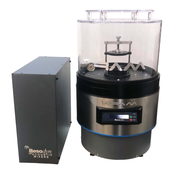
The overall assembly comprises: the Resonator, Cover, Umbilical Cables and Power Supply. Note: An optional Vessel Hold-down Fixture and a variety of vessel sizes are available from Resodyn Acoustic Mixers; see the ACCESSORIES Section 14 at the end of this Manual. Page 6... -
Page 7: Resonator
LabRAM Users Manual – Revised 3/18/11 5.2 Resonator The Resonator is the primary driver in your RAM mixer system. Your vessel, containing your mix media, attaches to the Top Plate. The Resonator, a powerful unit in a small package, works in a resonant mode to provide efficient energy transfer to the mix media in your vessel. - Page 8 LabRAM Users Manual – Revised 3/18/11 Cover. The Cover is cast acrylic. Its purpose is to contain fluid and debris if a vessel breaks during operation. A second purpose is to prevent a person from touching moving parts while the mixer is operating.
-
Page 9: Power Supply And Control
LabRAM Users Manual – Revised 3/18/11 Power Supply and Control The Power Supply and Control is separate from the Resonator and can be located remotely, in order to minimize space occupied on your lab bench. The Power Supply provides power to the Resonator. - Page 10 LabRAM Users Manual – Revised 3/18/11 Main Power Switch. The Main Power Switch cycles power from the A.C. Power Entry socket. The switch may be left ON continuously. Power may then be switched ON or OFF at the Resonator switch. Note: Both power switches must be in the ON position for the machine to operate.
-
Page 11: Standard Vessel Fixture And Vessels
5.4 Standard Vessel Fixture and Vessels Vessels of various sizes and a Hold-down Fixture are available through Resodyn Acoustic Mixers. Other vessel applications are adaptable to the LabRAM system. We can design a custom Hold- down Fixture to handle most any shape of vessel for your particular mixing application. -
Page 12: Theory Of Ram Mixing
LabRAM Users Manual – Revised 3/18/11 THEORY OF RAM MIXING ® ResonantAcoustics uses a proprietary method to create a mechanical system, designed to operate at a resonant frequency of ® the mechanical system. One advantage ResonantAcoustics over other mixing systems is the use of high-intensity acoustic energy. - Page 13 LabRAM Users Manual – Revised 3/18/11 Now that we’ve discussed how your payload affects the mixer, let’s look at the mixing process. The mixer operates at a mechanical frequency generally between 58 Hz and 65 Hz, and will accelerate a payload up to 100 G’s.
-
Page 14: Setup
LabRAM Users Manual – Revised 3/18/11 mass causes a shift in the resonant frequency, we have built in a resonant tracking feature, “Smart Mixing Technology,” (SMT). SMT controls the mixer and keeps it operating on the resonant peak, even if the peak changes. You can also operate the mixer in a manual mode by turning off SMT. -
Page 15: Position The Power Supply
LabRAM Users Manual – Revised 3/18/11 7.2 Position the Power Supply CAUTION Position the Power Supply The Power supply weighs 40 lbs and must near the Resonator, under be located in a secure position away from your Lab work bench, in potential liquid spills. -
Page 16: Connecting The Power Supply To The Resonator
LabRAM Users Manual – Revised 3/18/11 7.3 Connecting the Power Supply to the Resonator To connect the Power Supply to the Resonator, refer to Figure 3 and Figure 4. Note: There is a RS232, 9 pin sub D connector. It is a serial port that is connected to a P.C. -
Page 17: Attach The Hold-Down Fixture
LabRAM Users Manual – Revised 3/18/11 7.4 Attach the Hold-Down Fixture Mounting holes for attaching the LabRAM Hold-Down Fixture, or a custom fixture, are provided in the Top Plate of the Resonator. Specific dimensions for the Top Plate mounting hole placements are defined in TECHNICAL SPECIFICATIONS Section 12.3. -
Page 18: Install Vessel
¼-20 socket head cap screws into the Top Plate. 7.5 Install Vessel To install Resodyn Acoustic Mixers’ supplied vessels into the fixture refer to Figure 6. Figure 6: Vessel in Hold-Down Fixture Insert one of the Vessel Spacers (if required) into the bottom of the fixture as shown. -
Page 19: Install Cover
LabRAM Users Manual – Revised 3/18/11 7.6 Install Cover To install the Cover to the Resonator refer to Figure 7. COVER SAFTY INTERLOCK SWITCH RING Figure 7: Installing the Resonator Cover Install the Cover into the slot located on the Top Ring of the Resonator. -
Page 20: Operation
LabRAM Users Manual – Revised 3/18/11 OPERATION 8.1 Turn on Power To turn on the power to the Power Supply and Resonator refer to Figure 8. Figure 8: Turning on the Power Supply and Resonator Turn on the power to the Power Supply by toggling the rocker switch on the rear of the Power Supply UP, to the “ON”... -
Page 21: User Interface Menus
LabRAM Users Manual – Revised 3/18/11 8.2 User Interface Menus R E S O D Y N A C O U S T I C M I X E R S START UP SCREEN V I B R A T I O N O F F I N T E N S I T Y 0 1 0 . -
Page 22: Startup And Mixing Procedure
LabRAM Users Manual – Revised 3/18/11 8.3 Startup and Mixing Procedure Mixing requires an iterative approach. Once the correct intensity level is achieved, it can be stored. To begin mixing follow the steps outlined below. WARNING Do not attempt to remove the Cover or override the SAFETY INTERLOCK SWITCH located on the Top Ring of the Resonator while operating. - Page 23 LabRAM Users Manual – Revised 3/18/11 Press the MENU button until FREQ AUT appears. Then using the ARROW keys, change AUT to MAN. Next, using the ARROW keys, set the frequency to 60.00 Hz. Press the START button. Notice the top “Status” line changes from VIBRATION OFF to ACCELERATION XXX G’s.
-
Page 24: Automatic Countdown Timer
LabRAM Users Manual – Revised 3/18/11 the mass of your payload and the damping associated with it. This was explained in THEORY OF RAM MIXING Section 6. Press the MENU button until INTENSITY appears. Change the intensity from 015.0 % to 025.0 %. Notice in the example below, the acceleration changed from 020 G’s to 030 G’s (actual numbers may vary). -
Page 25: Error Handling
LabRAM Users Manual – Revised 3/18/11 determined period of time, and the mixer will automatically shut itself off. To use this feature, follow the steps outlined below. If your mixer is running, press the STOP button. This will turn the VIBRATION OFF. - Page 26 LabRAM Users Manual – Revised 3/18/11 In the event that the mixer is improperly operated this error will be momentarily displayed and the power to the force transducer will be interrupted. The cause of this error is related to operation outside of safe machine parameters (outside of the prescribed duty cycle).
- Page 27 LabRAM Users Manual – Revised 3/18/11 If the previous solutions do not stop reoccurrence of the condition, check the Resonator Fuse found on the back of the Power Supply. Only replace with recommended fuse if required. To restart the mixer, follow the procedures in STARTUP and MIXING PROCEDURE Section 8.3.
-
Page 28: Vacuum Option
LabRAM Users Manual – Revised 3/18/11 9 VACUUM OPTION 9.1 Introduction to the LabRAM Vacuum Option The vacuum option adds the benefit of mixing in vacuum to the LabRAM, thus providing for protection of reactive materials as well as eliminating gas incorporation into the materials during mixing. This section is intended to inform the reader on the set up and use of the vacuum option for the LabRAM mixer. -
Page 29: Vacuum Set Up
LabRAM Users Manual – Revised 3/18/11 9.3 Vacuum Set Up 9.3.1 Follow the vacuum pump manufacturer’s instructions on setup of pump. This manual can be found in the same shipping container as the vacuum pump. 9.3.2 Connect 1/4” poly tubing from pump to trap. See Figure 11. Trap should be placed on a flat relatively level surface. - Page 30 LabRAM Users Manual – Revised 3/18/11 9.3.4 Install the LabRAM mounted gauge (just inside the outer ring) into the two predrilled holes as shown in Figure 13. DO NOT attempt to mount the gauge directly to the payload plate. Figure 13. Gauge mounted to LabRAM 9.3.5 Connect 1/8"...
-
Page 31: Vacuum Operation
LabRAM Users Manual – Revised 3/18/11 9.4 Vacuum Operation Operation of the vacuum option is very intuitive. However the development of a process to mix your materials is not necessarily as simple. Experimentation will be required to develop and optimize the use of the LabRAM and vacuum process to your specific needs. -
Page 32: Vacuum Maintenance
LabRAM Users Manual – Revised 3/18/11 volatiles / mass from leaving the mixing vessel (jar) but pressure may fade. 9.4.8 To remove vacuum from the jar simply turn the pump off and open the valve. It is recommended that the vacuum remain on until the mixing is complete and the mixer is either off or at 0.0% intensity. - Page 33 LabRAM Users Manual – Revised 3/18/11 9.6 Vacuum Technical Specifications Vacuum Pump: Displacement 2 CFM 1.5 Torr (29.78”Hg) Final Pressure Motor 0.2HP/60Hz TEFC Voltage 110VAC/1 Phase Speed 3400 RPM Noise Level (@ 3 feet) 60dBA Oil Type None Weight 12Lbs ¼”...
-
Page 34: Vacuum Technical Specifications
LabRAM Users Manual – Revised 3/18/11 TROUBLE SHOOTING Problem: Then check: User Interface does Is the Power Supply switch on? not light up when Is the A.C. cord plugged in firmly? Resonator Power Are both Umbilical cords are firmly switch is turned ON. connected to the Resonator and Power Supply? 115 volts at wall outlet... - Page 35 LabRAM Users Manual – Revised 3/18/11 Vacuum pump runs Check oil level in pump. Check but no vacuum or vacuum pump manufacturer’s owners not enough vacuum manual. Check valve position on vacuum trap. Vertical is vacuum off. Horizontal is vacuum on. Check vacuum regulator.
-
Page 36: Maintenance
LabRAM Users Manual – Revised 3/18/11 Vacuum tubing is Try maintenance procedures. See Section 11 “Maintenance” in this clogged manual. Replace all external / visible tubing as required. Consult factory if problem not resolved. Do not attempt to open the LabRAM’s case. -
Page 37: Driver Harness
LabRAM Users Manual – Revised 3/18/11 replacement part is listed in the ACCESSORIES Section 14. Figure 15 shows the Resonator enclosure with the bottom removed and the location of the harness. 11.3 Driver Harness Inside the Resonator, mounted to the bottom of the Voice Coil Driver, is an electric driver harness that powers the Driver. -
Page 38: Technical Specifications
LabRAM Users Manual – Revised 3/18/11 TECHNICAL SPECIFICATIONS 12.1 General Mix Capacity: 500 grams Mixture Media: liquids, powders, slurries Mixture Temperature: 10 to 50ºC 5 – 100 G Acceleration: Duty Cycle 100% intensity 80-100G continuous 58 – 68 Hz Harmonic Frequency: Vessel Position: top mount Vessel Usability:... -
Page 39: Resonator Enclosure
LabRAM Users Manual – Revised 3/18/11 12.2 Resonator Enclosure The Resonator weighs 130 lbs. Page 39... -
Page 40: Resonator Top Plate Fixture Mounting
LabRAM Users Manual – Revised 3/18/11 12.3 Resonator Top Plate Fixture Mounting The Resonator Top Plate is made from aluminum. Steel inserts are provided in the four locations shown for mounting a vessel fixture. Torque the fasteners to 8 ft-lbs. Do not exceed 8 ft-lbs or you risk stripping the threads. -
Page 41: Power And Control Supply
LabRAM Users Manual – Revised 3/18/11 12.4 Power and Control Supply The Power and Control Supply weighs 40 lbs. Page 41... -
Page 42: Materials Of Construction And Chemical Compatibility
LabRAM Users Manual – Revised 3/18/11 12.5 Materials of Construction and Chemical Compatibility Definitions: Inorganic acids: hydrochloric, sulfuric, phosphoric, etc. Organic acids: citric, acetic, etc. Inorganic bases: alkali, sodium hydroxide, potassium hydroxide, etc. Aromatic hydrocarbons: toluene, xylene, etc. Ketones: MEK, acetone, etc. Esters: ethyl acetate, methyl benzoate, etc. - Page 43 LabRAM Users Manual – Revised 3/18/11 Halogenated and aromatic hydrocarbons Esters Ketones Aliphatic hydrocarbons such as greases and oils VESSELS – Polymeric: Note: Vessel information is provided for reference only. No claims are made regarding their durability or chemical compatibility with your specific mixtures.
- Page 44 LabRAM Users Manual – Revised 3/18/11 JAR VACUUM LID – Black Delrin Resistant to: Water, hydrocarbons, fuels, solvents and neutral chemicals Do not use with: Acids and strong bases JAR VACUUM LID FILTER – Polyester Resistant to: Water, organic solvents, petroleum oils, alkalies, organic acids, and mineral acids JAR VACUUM LID FILTER HOOK ATTACHMENT –...
-
Page 45: Service Plan
You may also contact our Service Department at: (406) 497-5333 To return components to Resodyn Acoustic Mixers Corporation for service, call our Technical Service Department for an RMA number. Re-package the component in the original shipping carton. Include the RMA number on the shipping label. -
Page 46: Accessories
LabRAM Users Manual – Revised 3/18/11 14 ACCESSORIES ITEM DESCRIPTION VIEW PART NUMBER Cover 100239 Hold-down fixture 100312 Vessel Spacer 100307 Vessel Spacer Half Height 100355 8 OZ Vessel 000073 16 OZ Vessel 000075 Custom fixture design and Please call engineering services 6’... - Page 47 LabRAM Users Manual – Revised 3/18/11 6’ Umbilical Power Harness 100289-6 12’ Umbilical Power 100289-12 Harness A.C. Power Supply Cable Please call Accelerometer harness 100239 Driver harness 100333 Vacuum Pump 000316 Vacuum Trap assembly 100535 Page 47...
- Page 48 Vacuum Lid, 8oz 100536 Vacuum Lid Filter, 8oz 100542 POLY TUBING – Commercially Polyethylene available 1/8” and 1/4” O.D. Gasket Seals for Vacuum 100832 Resodyn Acoustic Mixers 130 North Main Sreet, Suite 630, Butte, MT 59701 406-497-5333 Page 48 www.resodynmixers.com info@resodyn.com...
Need help?
Do you have a question about the LabRAM ResonantAcoustic and is the answer not in the manual?
Questions and answers