Table of Contents
Advertisement
Quick Links
Product Information
Product model: ZD120E Series
Product name: Patient Monitor
Manufacturer
Shenzhen Hexin ZONDAN Medical Equipment Co., Ltd.
Registered/Production address:
Floor 14, Block D, Dianlian Technology Building, the Crossing between South Circle
Road and South Fuli Road ,Guangming District,518106 Shenzhen PEOPLE'S
REPUBLIC OF CHINA
Tel: +86 755 26865970
Edition
Fourth Edition: October 2021
Version: V1.4
MEDHealth supplies (Pty) Ltd
All Rights Reserved.
Distributor
MEDHealth Supplies (Pty) Ltd
Corner of Barbara and North Reef Road
Elandsfontein, Henville, 1429, Germiston, Johannesburg, Gauteng, South Africa
Reg No.: 2021/385832/07
E-mail: admin@medhealthsup.com
Regulatory and Safety Specifications
Standard
The product is made under the ISO13485 quality system certified by TUV PS. The
product has passed the CE certification.
Declaration
The ZD120E Patient Monitor is a Class IIb device and complies with the requirements of
the Council Directive 93/42/EEC concerning medical devices and carries CE-marking
accordingly.
Authorized EU Representative
Shanghai International Holding Corp.GmbH (Europe)
Eiffestrasse 80, 20537 Hamburg, Germany
Tel: 0049-40-2513175 Fax: 0049-40-255726
Fax: +86 755 26860497
Telephone: +27 10 013 3010
I
ZD120D/ ZD120E User Instruction Manual
Fourth Edition: October 2021
Version: V1.4
Advertisement
Table of Contents

Related Manuals for Shenzhen Hexin Zondan Medical Equipment ZD120E Series

Summary of Contents for Shenzhen Hexin Zondan Medical Equipment ZD120E Series
- Page 1 Product Information Product model: ZD120E Series Product name: Patient Monitor Manufacturer Shenzhen Hexin ZONDAN Medical Equipment Co., Ltd. Registered/Production address: Floor 14, Block D, Dianlian Technology Building, the Crossing between South Circle Road and South Fuli Road ,Guangming District,518106 Shenzhen PEOPLE'S...
- Page 2 Explanation of Symbols The following symbols appear on the monitor and packaging. Table 1 Monitor and Packaging Symbols Symbol Description Symbol Description Caution, consult accompanying Temperature limitations documents 9 3 % Keep dry Humidity limitations 1 0 % 107.4kPa Atmospheric pressure Fragile, handle with care limitations...
- Page 3 Table 1 Monitor and Packaging Symbols (continue) Symbol Description Symbol Description applied part: including F applied part BF applied part: including F (float/insulation) applied part (float/insulation) defibrillation-proof function. CF applied part: including F applied part (float/insulation) Fuse defibrillation-proof function. Protective Ethernet port grounding Video output...
- Page 4 Table 2 Safety Standards (continue) Parameter Specification Sterilization and disinfection As recommended by manufacturer Mode of operation Continuous Product Support and Warranty Information The manufacturer warranties the ZD120E Patient Monitor for 12 months. Keep the packing case for transport, storage, or maintenance. The manufacturer is responsible for the safety, reliability, and performance of the monitor when the: •...
- Page 5 E-mail: service1@zondan.com Service and support are available in Chinese and English only. Before calling for service, note the following information: • Model and serial number of the monitor • Monitor problem Safety Conventions The manual uses the following conventions for Notes, Cautions, and Warnings. Note —...
- Page 6 rate meter alarms. Keep pacemaker patients under close surveillance. See this manual for disclosure of the pacemaker pulse rejection capability of this instrument. Never use the monitor during MRIs or CT scans. Never use cables with exposed conductors. Only use undamaged cables and connectors to avoid personal injury.
- Page 7 60601-1-1 medical electrical standards. If patient data is lost, closely monitor the patient, or replace the monitor immediately until the monitor restores normal function again. Monitoring will be stopped while user configurations will be saved automatically when the monitor is powered off. To reduce the hazard of burns in high-frequency surgical neutral connections, the leads and connectors must be located away from the surgical site.
-
Page 9: Table Of Contents
Contents Contents ............................1 Chapter 1 Overview ........................6 Indications for Use ........................6 Intended Use ..........................6 Configurations ..........................7 Chapter 2 Basic Operation ......................8 Before You Begin ......................... 8 2.1.1 Unpacking the Equipment ....................8 2.1.2 Setting up the Monitor ....................... 8 2.1.3 Networking Capabilities .................... - Page 10 3.4.3 Adjusting the Alarm Volume ................... 27 Setting Alarm Limits ........................27 3.5.1 Setting Individual Alarm Limits ..................27 3.5.2 Restoring Default Alarm Limits ..................28 Reviewing Alarm Events ......................28 Chapter 4 Monitoring ECG ...................... 30 Placing the Electrodes ........................ 30 4.1.1 Changing a Lead Set ......................
- Page 11 Measurement Limitations ......................47 The NIBP Display ........................47 Selecting the NIBP Measurement Modes ................... 47 Selecting the NIBP Interval Time ....................48 Changing the NIBP Unit......................48 Viewing NIBP Measurement Data ..................... 49 Changing the NIBP Alarm Settings .................... 49 7.8.1 Changing the NIBP Alarm Record Settings.
- Page 12 Chapter 11 Review ........................62 11.1 Trend Table display ........................62 11.2 Trend Graph display ........................62 11.3 NIBP Review ..........................62 11.4 Waveform Recall ........................63 11.5 Alarm Recall (Physiological alarm) ................... 63 11.6 Technical Alarm Event Recall ....................64 Chapter 12 Drug Calculation....................
- Page 13 Power Specifications ........................83 Display Specifications ........................ 84 B.10 Recorder Specifications ......................84 B.11 Physical Specifications ....................... 84 B.12 Environmental Specifications ..................... 85 B.13 Interface Specifications ......................85 C Alarm ............................ 86 The physiological alarm information ..................86 The Technical alarm information....................87 D Glossary ..........................
-
Page 14: Chapter 1 Overview
Chapter 1 Overview The ZD120E Patient Monitor is used for monitoring, recording, and alarming of multiple physiological parameters of adults, pediatrics, and neonates. The monitor stores data in trend and event databases. You can view measurement trend graphs and alarming events to help you identify changes in the patient's physiological condition. -
Page 15: Configurations
1.3 Configurations The following table lists the available configurations, and the standard features as well as optional features. In the table, a solid circle indicates this feature is standard, a half solid half hollow indicates this feature is optional and a hollow circle indicates this feature is unavailable. -
Page 16: Chapter 2 Basic Operation
Chapter 2 Basic Operation This chapter describes how to set up and begin using the ZD120E Patient Monitor. 2.1 Before You Begin Before patient monitoring, ensure that the monitor is in good condition and used in the proper environment. 2.1.1 Unpacking the Equipment Unpack the equipment and ensure that you have the following: –... -
Page 17: Monitor Power Supply
Network setup of the ZD120E Patient Monitor is not user configurable. Please contact your service personnel. 2.1.4 Monitor Power Supply You can power the monitor with either an AC power source or its internal battery. You can switch back and forth between supplies without powering off the monitor. When the monitor is connected to an AC power source, you can turn on and operate the patient monitor. -
Page 18: The Front Panel
2.2.1 The Front Panel Figure 2-1 Front Panel The following table describes the controls on the monitor. Table 2-1 Monitor Controls Item Icon Meaning Description Number Press and hold for two seconds to turn the monitor on Power button or off. Steady green: the monitor is powered on. -
Page 19: The Rear Panel
Alarm Led See chapter 3, Alarms for more information. 2.2.2 The Rear Panel The following figure shows the rear panel of the monitors. Figure 2-2 Rear Panel The following table describes each item on the rear panel. Table 2-2 Rear Panel Item Item Name... -
Page 20: The Bottom Panel
Figure 2-3 Side Panels The following table describes the side panels. Table 2-3 Side Panels Item Item Name Number TEMP1 TEMP1 connector TEMP2 TEMP2 connector ECG/RESP ECG connector IBP1 IBP1 transducer cable connector input connector NIBP NIBP cuff hose connector probe connector output connector IBP2... -
Page 21: Screen Display
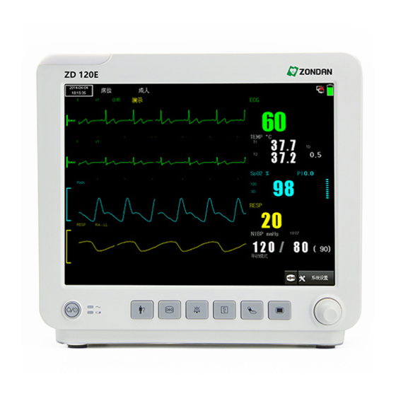
2.3 Screen Display The monitor displays parameters, waveforms, and relevant information of patient measurements. The main screen display could look different, depending on the configuration of the monitor. You can select a main screen display according to your needs. The following figure shows a typical screen display. Figure 2-5 Example of ZD120E Screen Display The following table describes the screen display. -
Page 22: Icons On Menu Area
2.3.1 Icons on menu area Table 2-5 Icons Description Meaning Icon Description y selecting it you can unfold the softkeys Information All waveforms, alarm, NIBP, graphic and tabular trends review review Volume Set up volume Alarm Setup Alarm Limits Setup Standby Enter standby mode Brightness... -
Page 23: Using The Dynamic Trend Screen
The following figure shows an example of the screen display when is selected: Big Number Figure 2-6 Example of Big Number Display To display Big Number screen: Method 1: Press to unfold the softkeys at menu area. Press , Face Switch window appears. Select Big Number and press it. -
Page 24: Using Standard Mode
The following figure is an example of the dynamic trend screen. Figure 2-7 Example of Dynamic Trend Screen To display dynamic trend screen: Method 1: Press to unfold the softkeys at menu area. Press , Face Switch window appears. Select Dynamic Trend and press it. Exit the menu. -
Page 25: Displaying The Oxycrg Screen
To display Standard interface screen: Method 1: Press to unfold the softkeys at menu area. Press , Face Switch window appears. Select Standard Interface and press it. Exit the menu. Method 2: Press Key on the front panel, Main screen window appears. Select Setup at Main screen window. -
Page 26: Displaying The Other Bed Screen (Optional)
To configure the time span of the OxyCRG: Press to unfold the softkeys at menu area. Press , Face Switch window appears. Select for OxyCRG. Press OxyCRG area, OxyCRG Setup window appears. Select Time Select, there are options of 1 min, 2 min and 4 min. Exit the menu. -
Page 27: Using Standby Mode
To display the Other Bed View Screen: Method 1: Press to unfold the softkeys at menu area. Press , Face Switch window appears. Select Other Bed View and press it. Exit the menu. Method 2: Press Key on the front panel, Main screen window appears. Select Setup at Main screen window. -
Page 28: Changing The Waveform Speed
In standby mode, the monitor: • blanks the screen and displays the message Standby • continues charging the battery connected to AC power. • saves trend data. • stops patient monitoring. • stops sending patient data and alarms to the Central Monitoring System. To enter standby mode: Press to unfold the softkeys at menu area. -
Page 29: Freezing The Waveforms
Select Color Custom. Select color option, Green, Red, White, Purple, Cyan, Yellow and Blue are available. Exit the menu. 2.5.9 Freezing the Waveforms You can freeze the real-time waveforms to check measurements more closely. When monitoring. • Press the Waveform Freeze key on the front panel to freeze waveforms. -
Page 30: Changing The Brightness
There are two ways to change date and time Method 1: Press Main Menu Key on the front panel, Main menu appears. Select Setup. Setup window appears. Select Time, Time Setup window appears. Change date and time information. Select icon to confirm and back to previous menu. - Page 31 User’s Manual MHSZD120E Version: 1.4 October 2021...
-
Page 32: Chapter 3 Alarms
Chapter 3 Alarms This chapter describes how to configure alarms, including alarm levels and alarm limits. The alarm information in this chapter applies to all measurements. Alarms for specific measurements are described in their respective chapters. Alarms sound when the monitor senses an irregular condition either in monitor operation or alarm limits. -
Page 33: Flashing Numeric Values
Table 3-1 Alarm LEDs (continue) Light Color Medium priority alarm Yellow, slow flicker Yellow, keep lighting without Low priority alarm flicker Reminder light Blue, flicker Note — If more than one alarm condition is active, the monitor signals the most severe. 3.3.2 Flashing Numeric Values When a parameter value exceeds the preset alarm limits, the corresponding numeric flashes. -
Page 34: Turning On/Off Audible Alarms
Warning Do not rely exclusively on the audible alarm system for patient monitoring. Changing the alarm volume to a low level or turning it off during patient monitoring could result in patient danger. The most reliable method of patient monitoring combines close personal surveillance with correct operation of monitoring equipment. -
Page 35: Adjusting The Alarm Volume
Alarm Silence remind area. Setup Alarm Silence for 1 or 2 minutes. Press key on the front panel, the Main menu appears. Select Setup, the Setup menu appears. Choose 1 min or 2 min at Alarm Silence Time. To activate all audible alarms before the timeout counter reaches , press the Alarm 00:00 Silence... -
Page 36: Restoring Default Alarm Limits
Select Alarm Level, High and Medium are options. Select alarm limit at Alarm High Limit and Alarm Low Limit. Exit the menu. Method 2: Enter Alarm Setup at numeric pane area Select Alarm ON/OFF. Select Alarm Level, High and Medium are options. Select alarm limit at Alarm High Limit and Alarm Low Limit. - Page 37 Press to watch earlier or later alarm event. Press to observe trend data with different parameters. Exit the menu. Alarm events and time are shown on the left of the physiological alarm window. The details of the alarming events which selected will be displayed on the right include alarming types, time, and waveforms.
-
Page 38: Chapter 4 Monitoring Ecg
Chapter 4 Monitoring ECG This chapter describes ECG monitoring on the ZD120E Patient Monitor. An electrocardiogram (ECG) monitors the electrical activity of the heart. The Monitor processes these electrical signals and displays an ECG waveform on the screen with its numeric on the numeric pane. - Page 39 Table 4-1 Lead Description (continue) AAMI Lead Color Lead Color Brown White Brown/Red White/Red Brown/Yellow White/Yellow Brown/Green White/Green Brown/Blue White/Brown Brown/Orange White/Black Brown/Violet White/Violet When placing electrodes, choose a flat, non-muscular site where the signal will not be affected by movement or bones. Correct lead placement is always important for accurate diagnosis, especially in the precordial leads, which are close to the heart.
-
Page 40: Changing A Lead Set
The following figure shows the 5-lead ECG electrode locations: AAMI Figure 4-2 Five-Lead Locations 4.1.1 Changing a Lead Set A pair of electrodes forms a lead. Each lead provides a different view of the same cardiac activity. You can select a proper lead mode and an ECG lead. The selected lead mode and ECG lead displays on top of the ECG waveform. -
Page 41: Connecting Ecg Cables
due to a poor connection of the neutral electrode. Warning Electrosurgical equipment must be properly grounded to avoid a current inflow hazard. This can cause interference on the ECG signal. 4.1.3 Connecting ECG Cables To connect ECG cables: Attach the clips or snaps to the electrodes before placing them. If you are not using pre-gelled electrodes, apply electrode gel to the electrodes before placement. -
Page 42: Displaying Seven Ecg Waveforms
10 = Heartbeat indicator 11 = Time interval (once per second) 12 = PVCs numeric pane label 13 = PVCs value 4.2.2 Displaying Seven ECG Waveforms Depending on options, the monitor can display seven ECG waveforms at the same time and the heart rate value in ECG numeric pane. -
Page 43: Changing The Ecg Waveform Speed
Table 4-3 ECG Scale When the ECG Gain is The scale height ×0.25 is 2.5 mm. ×0.5 is 5 mm. ×1 is 10 mm. ×2 is 10 mm, the calibration bar change to white, mark 0.5mV ×4 is 10 mm, the calibration bar change to white, mark 0.25mV Auto Varies in step with the ECG gain. -
Page 44: Changing The Ecg Mode
The options of Heart Rate Volumes are 0,1,2,3,4. Exit the menu. 4.5 Changing the ECG Mode The monitor has three ECG modes for different monitoring environments: Monitor . The current ECG mode displays on top of the ECG1 channel. Operation Diagnostic To change the ECG mode: Enter ECG Setup menu at numeric panes. -
Page 45: The Arrhythmia Display
4.7.3 The Arrhythmia Display The following figure shows an example of the ARR waveform and the numeric pane: Figure 4-7 ARR Waveform and Numeric Pane 1 = 1 mV calibration bar 2 = ECG lead of ARR occurrence 3 = ECG gain of ARR occurrence 4 = ECG mode of ARR occurrence 5 = ARR waveform 6 = ECG numeric pane label... - Page 46 conductive parts, or with ground. Ensure that all of the ECG electrodes are attached to the patient. For pacemaker patients, the monitor can continue to count pacemaker rate during cardiac arrest or some arrhythmias. Do not rely entirely upon the monitor’s alarm. Keep pacemaker patients under close surveillance.
-
Page 47: Chapter 5 Monitoring Respiration
Chapter 5 Monitoring Respiration Respiration can be measured using one of the following methods: • ECG. The monitor measures the thoracic impedance between two ECG electrodes on the patient’s chest. Changes in the impedance due to thoracic movement produce the Resp waveform on the monitor screen. The monitor counts the waveform cycles to calculate the respiration rate (RR). -
Page 48: Changing The Respiration Display
Figure 5-1 Resp Waveform and Numeric Pane 1 = Resp waveform label 2 = Resp lead 3 = Resp waveform 4 = Resp numeric pane label (respiration rate unit) 5 = Resp rate Note — If the detected respiration rate is close to the heart rate, the alarm message Beat displays. -
Page 49: Changing The Respiration Alarm Settings
of apnea, particularly the apnea of prematurity and apnea of infancy, has not been established. If operating under conditions according to EMC Standard EN 60601-1-2 (Radiated Immunity 3V/m), field strengths above 1V/m might cause erroneous measurements at various frequencies. Therefore, avoid using electrically radiating equipment in close proximity to the respiration measurement unit. -
Page 50: Chapter 6 Monitoring Spo
Chapter 6 Monitoring SpO Pulse oximetry uses a motion-tolerant signal processing algorithm. It provides these measurements: • Oxygen saturation of arterial blood (SpO ) percentage of oxygenated hemoglobin in relation to the sum of oxyhemoglobin and deoxyhemoglobin. • Pleth waveform – A visual indication of a patient’s pulse. •... -
Page 51: Measuring Spo
6.4 Measuring SpO Note — Clean the sensor surface with 70% ethanol before and after use. Never immerse the sensor in liquid. To start monitoring SpO Select a sensor of the correct type and size and attach it to the patient site. Connect the SpO cables and ensure a good connection. -
Page 52: Changing The Spo Display
1 = SpO waveform label 2 = Pleth wave 3 = SpO numeric label 4 = SpO unit 5 = PR numeric label 6 = PR value 7 = Perfusion numeric label 8 = Perfusion index value 9 = Perfusion bar graph 10 = SpO Alarm high and low limit 11 = SpO... -
Page 53: Safety Information
Set up PR limits at PR A Limit and PR Low Limit. Exit the menu. 6.11 Safety Information Warning Continuous monitoring might make skin red, blistered, or cause compression necrosis. This is especially true for neonates or patients with perfusion disorder or unhealthy skin. -
Page 54: Chapter 7 Monitoring Nibp
Chapter 7 Monitoring NIBP The monitor uses the oscillometric method for measuring NIBP. The principle of the Oscillometric method of measuring blood pressure is stopping the arterial blood stream with the pressure of the inflation cuff. As the cuff pressure decreases, the air pressure oscillation wave caused by the blood stream can be measured in the cuff. -
Page 55: Measurement Limitations
7.2 Measurement Limitations NIBP measurements are impossible with heart rate extremes of less than 40 bpm or greater than 300 bpm, or if the patient is on a heart-lung machine. The measurement may be inaccurate or impossible: • If a regular arterial pressure pulse is hard to detect. •... -
Page 56: Selecting The Nibp Interval Time
for continuous NIBP monitoring of supervised patients in special cases. The Stat monitor displays in the NIBP numeric pane and starts to count down after starting the Stat first NIBP measurement.04:59 will appear also. When mode times out or mode pauses due to a measurement error or technical Stat Auto malfunction, the monitor switches to... -
Page 57: Viewing Nibp Measurement Data
7.7 Viewing NIBP Measurement Data After a complete NIBP measurement, the NIBP measurement value displays in the NIBP numeric pane. When no menu is on the monitoring screen, choose NIBP Review menu to view the data in the NIBP list. The monitor displays up to 1500 groups of measurement data in time sequence, with the latest reading at the top. - Page 58 Use clinical judgment before using NIBP monitoring on patients with serious blood clot disease due to the risk of hematoma in the limb with the cuff. User’s Manual MHSZD120E Version: 1.4 October 2021...
-
Page 59: Chapter 8 Monitoring Temperature
Chapter 8 Monitoring Temperature This chapter describes how to monitor body temperature. The monitor measures temperature through the sensor temperature and electrical impedance. The monitor can measure two temperatures simultaneously, TEMP1 and TEMP2. The monitor displays the temperature values and the difference between these two temperatures in the numeric panes. -
Page 60: The Temperature Display
8.4 The Temperature Display The monitor displays two temperature values in the numeric pane. The following figure shows an example of a temperature numeric pane. Figure 8-1 Temperature Numeric Pane 1 = TEMP Numeric Pane label 2 = TEMP value 3 = T1 label 4 = T2 label 5 = TD label... -
Page 61: Chapter 9 Monitoring Co
Chapter 9 Monitoring CO ) to monitor a patient’s respiratory and ventilation status. Measure carbon dioxide (CO The CO measurement produces: • A CO waveform. • An end tidal CO (Et CO ) value: the CO value measured at the end of the expiration phase. -
Page 62: Influencing Factors
Note — Always connect the airway adapter to the sensor before inserting the airway adapter into the breathing circuit. In reverse, always remove the airway adapter from the breathing circuit before removing the sensor. Always disconnect the cannula, the airway adapter, or the sampling tube from the sensor when not in use. -
Page 63: Setup Period
Exit the menu. Warning Be sure to set the compensation properly. Improper settings will result in erroneous CO reading. 9.4.2 Setup Period The counting period for could be a breath, 10s or 20s. To setup counting period: Enter CO Setup Menu at numeric pane. Click Other Setup, CO Setting window appears. -
Page 64: Removing Exhaust Gases From The System
9.5 Removing Exhaust Gases from the System When using the Micro stream CO measurement on patients who are receiving or have recently received anesthetics, connect the outlet to a scavenging system or to the outlet connector, to avoid exposing medical staff to anesthetic gases. 9.6 The CO Display The following figure shows an example of the CO... -
Page 65: Changing The Co Unit
Standby Mode when the monitor is not measuring CO to lengthen the module’s lifespan. To change the CO work mode: Enter CO Setup menu at numeric pane. Click Work Mode, select a needful work mode. The options are Standby Mode Work Mode Exit the menu. -
Page 66: Chapter 10 Monitoring Invasive Blood Pressure
Chapter 10 Monitoring Invasive Blood Pressure Invasive blood pressure (IBP), or direct blood pressure measurement, provides accurate blood pressure values of the cardio-artery area. IBP monitoring can track transient variations of arterial blood pressure; however, a catheter must be inserted through the skin into the blood vessel where skin damage can occur. -
Page 67: Zeroing The Pressure Transducer
Enter IBP Setup at numeric pane. Choose Channel 1 or Channel 2 at IBP Setup Menu. Choose the needful pressure label; refer to table 10-1. Exit the menu. Table 10-1 IBP Pressure Labels Label Description Label Description Arterial blood pressure Pulmonary artery pressure Central venous pressure Right atrial pressure... -
Page 68: Changing The Invasive Blood Pressure Waveform Display
Figure 10-1 IBP Waveform and Numeric Pane 1 = calibration bar 2 = CH1 pressure type 3 = IBP1 waveform 4 = IBP Numeric Pane label 5 = IBP unit 6 = Systolic pressure (CH1 in this example) 7 = Mean arterial pressure (CH1 in this example) 8 = Diastolic pressure (CH1 in this example) 10.7 Changing the Invasive Blood Pressure Waveform Display You can configure the monitor IBP display by changing the IBP settings. -
Page 69: Changing The Ibp Alarm Settings
To change the IBP unit: Enter IBP Setup menu at numeric area. Choose Unit. Select one needful IBP unit from mmHg and kPa. Exit the menu. Note — When you change the IBP unit, the change displays wherever pressure parameters are. 10.9 Changing the IBP Alarm Settings IBP alarms include alarms for SYS, DIA and MAP. -
Page 70: Chapter 11 Review
Chapter 11 Review 11.1 Trend Table display The Trend Table window displays patient data in a list format. To Trend Table: Press to unfold the softkeys at menu area. Click Review to enter Review Window. Select Trend Table at Review Window. Trend Table window appears. Choose RES. -
Page 71: Waveform Recall
in the NIBP retrospection. The recall screen may display 10 sets of measurement data. To NIBP Review: Press to unfold the softkeys at menu area. Click Review to enter Review Window. Select NIBP Review at Review Window. NIBP Review window appears. Press or , to the earlier or later measurement data Press Record to print NIBP review list. -
Page 72: Technical Alarm Event Recall
11.6 Technical Alarm Event Recall The steps of checking the technical alarm event recall: Press the area of alarm to enter technical alarm recall menu. Press to turn page for checking the technical alarm events earlier or later. Exit the menu. User’s Manual MHSZD120E Version: 1.4 October 2021... -
Page 73: Chapter 12 Drug Calculation
Chapter 12 Drug Calculation The monitor provides a Drug Calculation window to let you calculate a drug concentration, infusion rate, titration rate, and dosage calculation. You can also generate a titration chart for infusion speed and time. 12.1 Calculating the Drug Concentration Enter the following information before calculation: –... -
Page 74: Using The Titration Chart
⚫ Titration Rate: The unit of titration rate is . Titration rate = infusion rate x GTT/min volume per drop. To calculate the titration rate: Press the Main screen key on the front panel of the monitor Select Setup at Main menu Window. Setup window appears. Select Drug Calculation, Drug Calculation window appears Choose Volume per drop from GTT/ml or... -
Page 75: Chapter 13 Recording (Optional
Chapter 13 Recording (Optional) 13.1 About the Recorder The recorder can: ⚫ Could choose the type and amount of parameter to print. ⚫ The real-time parameters and waveform record. ⚫ Frozen print. 13.2 Loading the Recorder Note — Use only manufacturer-supplied thermal paper with a width of 112 mm. using the wrong paper can damage the recorder or cause it not to print Insert a roll of paper into the spindle. -
Page 76: Recording
recorder and ensure that the paper is correctly loaded, start printing. If no printout appears, the paper might be loaded backwards. Try reloading the paper. The cover of the screw Close recorder door Figure 13-4 closes the printer door To load the recorder paper: Pull at least 25 mm of the paper out of the door, removing any slack. - Page 77 • Use only manufacturer approved recorder paper. • Keep the recording strips in a dry, dark, and cool place. • Avoid exposure to: – High temperature, humidity, direct sunshine, and fluorescent lighting and radiation. – Ambient temperatures over 50℃. – Liquids. –...
-
Page 78: Chapter 14 Cleaning And Care
Chapter 14 Cleaning and Care This chapter gives general guidelines on the cleaning and care of your monitor and accessories. Use only the approved cleaning methods and agents listed in this chapter. The warranty does not cover damage caused by using unapproved substances. Cleaning methods described in this chapter have been tested by the manufacturer. -
Page 79: Cleaning The Accessories
14.2 Cleaning the Accessories When possible, clean the accessories according to the manufacturer’s instructions. Use the general guidelines in this chapter if you do not have specific product cleaning instructions. 14.2.1 Cleaning the Cables Dampen a soft cloth with one of the following cleaning agents: •... -
Page 80: Disinfecting The Monitor
for a short time . 14.3 Disinfecting the Monitor To avoid long-term damage to the equipment, do not disinfect unless directed by the hospital. Warning Never mix disinfecting solutions (such as bleach and ammonia) as hazardous gases may result . Clean the equipment before disinfecting. -
Page 81: Chapter 15 Maintaining The Battery
Chapter 15 Maintaining the Battery You can power the monitor with either an AC power source or its optional Lithium-ion battery. Warning Only use batteries specified by the manufacturer. Other batteries can cause monitor damage or personal injury. 15.1 Charging LED A battery symbol on the front panel indicates the charging LED. -
Page 82: Recharging The Battery
Push the battery into the compartment until it clicks into place. Install the battery cover and tightening the screw. Note — The monitor can use the battery specified by the manufacturer only, using other batteries might hurt the patient, user and monitor. Warning Ensure that the battery is completely inserted into the monitor and that the battery door is firmly closed. -
Page 83: Chapter 16 Maintenance And Troubleshooting
Chapter 16 Maintenance and Troubleshooting Warning Failure to implement a satisfactory maintenance schedule for this equipment may cause undue equipment failure and potential health hazards. If you meet a problem with any of the equipment, pls contact professional service personnel . 16.1 Inspecting the Equipment and Accessories Perform a visual inspection before every use. - Page 84 Table 16-2 ECG Problems Problem Solution • Check the patient’s ECG signal • Check/adjust the lead position • Check/reclean skin HR or ARR measurements inaccurate • Check/replace ECG electrode • Check ECG wave amplitude • Ensure that the electrode is in good contact with the patient.
-
Page 85: Disposing Of The Monitor
Table 16-4 NIBP Problems (continue) Problem Solution displays in the NIBP This error can be caused by system self-testing, Measurement Error numeric pane. excessive patient and/or limb movement, or air leakage. Consult your service representative. Table 16-5 TEMP Problems Problem Solution There is no temperature displayed. -
Page 86: A Accessories
A Accessories This appendix describes the accessories that are compatible with the ZD120E Patient Monitor. Table A-1 Accessories list Accessories Specification ECG cable A5037-EC1 Neonate ECG Electrodes, 2417-0003 ECG Electrode Adult ECG Electrodes, 2417-0001 , A1802-SA126PV Adult Finger SpO Sensor A1802-SP126PV SpO2 Sensor Pediatric Finger SpO... -
Page 87: B Specifications
B Specifications This appendix describes the specifications of the ZD120E Patient Monitor. B.1 ECG/ST/Arrhythmia Specifications The following table describes the ECG/ST/arrhythmia specifications. Table B-1 ECG Specifications Parameter Specifications CMRR (Common mode rejection ≥ 90 dB ratio) Adult high alarm limit: 17bpm - 300bpm Adult low alarm limit: 15 bpm -298 bpm Pediatric/ Neonate high alarm limit: 17bpm - HR alarm range... -
Page 88: Respiration Specifications
Parameter Specifications Signal delay 0.5s Active electrode:< 100nA Auxiliary current (leads off detection) Reference electrode: < 900 nA Ventricular bigeminy: 80 bpm±2bpm Slow alternating ventricular bigeminy: 60 bpm ±2bpm Heart ratemeter accuracy response to irregular rhythm Rapid alternating ventricular bigeminy: 120 bpm ±2bpm Bidirectional systoles: 90 bpm±2bpm ≤... -
Page 89: Temperature Specifications
Because pulse oximeter measurements are statistically distributed, only approximately two-thirds of pulse oximeter equipment measurements can be expected to fall within the Arms value measured by a CO-oximeter. Note — It is not necessary to have a SpO calibration when the monitor is in use. The following table describes the SpO specifications. -
Page 90: Non-Invasive Blood Pressure Specifications
B.5 Non-invasive Blood Pressure Specifications The following table describes the NIBP specifications. Table B-5 NIBP Specifications Parameter Specification Measuring method Oscillometric method Measuring parameter SYS, DIA, MAP Measuring method Oscillometric method Measuring parameter SYS, DIA, MAP Unit mmHg or kPa Work mode Manual, Auto, Stat Cycle time... -
Page 91: Invasive Blood Pressure Specifications
Table B-6 CO Specifications (continue) Parameter Specification 0 mmHg- 40 mmHg (0 kPa- 5.33 kPa): ±2 mmHg (±0.3 kPa) 41 mmHg- 76 mmHg (5.47 kPa- 10.1 kPa): ±5 mmHg (±0.7 kPa) accuracy 77 mmHg- 99 mmHg (10.3 kPa- 13.2 kPa): ±10 mmHg (±1.3 kPa) Maximum: 50 ml/m + 15 ml/m Sample flow rate Minimum: 50 ml/m - 7.5 ml/m... -
Page 92: Display Specifications
Battery Power Parameter Specification Lithium ion Capacity 11.1 V/2400 mAh Charging time hours (to 90% battery capacity) ≥ 2 hours (with ECG, SpO measurement Typical operating time and NIBP measured every 15 minutes) Automatic (with charge protection feature) when the monitor is connected Charge mode to an AC power source. -
Page 93: Environmental Specifications
B.12 Environmental Specifications The following table describes the environmental specifications. Table B-13Environmental Specifications Parameter Specification ℃ ℃ Operating: 0 - 40 Temperature ℃ ℃ Storage: -20 for the device Operating: 15% - 80% (noncondensing) Relative humidity Storage: 10% - 93% (noncondensing) Operating: 59 kPa ~... -
Page 94: C Alarm
Alarms C.1 The physiological alarm information Table C-1 Physiological alarm information Alarm Source Level Reason and Solution information XX value has exceeded the high alarm XX Too High HIGH or MED limit or below the low alarm limit. Check the patient physiological status, XX Too Low HIGH or MED patient type and alarm limit setup. -
Page 95: The Technical Alarm Information
the patient, electrodes, cables and leads. Table C-1 Physiological alarm information (continue) Alarm Source Level Reason and Solution information The patient RR cannot measure since Resp Cardiac RESP HIGH heartbeat interrupts RESP. Check the Overlay (continue) patient, electrodes, cables and leads. The PR signal is too weak. - Page 96 ST2 Exceed Table C-2 Technical alarm information (continue) Source Alarm information Level Reason and Solution ST3 Exceed ST4 Exceed ST5 Exceed ECG parameter value is over range; please (continue) contact your service representative. ST6 Exceed ST7 Exceed ST8 Exceed Probe Off The SpO sensor disconnected from the patient or No Sensor...
- Page 97 Ambient atmospheric pressure is abnormal, Air Pressure Error confirm whether the environment is fit for monitor specification, if any special cause impact Table C-2 Technical alarm information (continue) Source Alarm information Level Reason and Solution The patient PR is too weak or cuff loose, Low Signal check the patient and replace the cuff site.
- Page 98 modified; please contact your service IBP2 Alarm Limit Error representative. IBP parameter value is over range; please IBP1 SYS Exceed contact your service representative. Table C-2 Technical alarm information (continue) Source Alarm information Level Reason and Solution IBP1 DIA Exceed IBP1 MEAN Exceed IBP parameter value is over range;...
- Page 99 PM 5V Too Low PM 3.3V Too High PM 3.3V Too Low Table C-2 Technical alarm information (continue) Source Alarm information Level Reason and Solution Check the printer whether connected, connect Recorder Door Open and print. Recorder Sensor No Paper Check whether no paper, install and print.
-
Page 100: D Glossary
D Glossary This appendix defines some terminology and abbreviations. D.1 Terminology Definitions Table D Terminologie Définitions Term Definition a/AO2 Alveolar-arterial oxygen AaDO2 Alveolar-arterial oxygen difference Anesthetic gas Aortic pressure Arrhythmia Arterial pressure Left arm augmented lead Right arm augmented lead Body surface area Blood temperature C.O. - Page 101 Table D Terminologie Définitions (continue) Term Definition Femoral artery pressure Gas parameter Halothane Heart rate Invasive blood pressure Intracranial pressure InCO Inspired carbon dioxide In N4O Inspired nitrous oxide Inspired oxygen Invasive blood pressure Isoflurane Left arm Left cardiac work LCWI Left cardiac work index Left leg...
- Page 102 Table D Terminology Definitions (continue) Term Definition RCWI Right cardiac work index RESP Respiration Right leg Respiration rate RVSW Right ventricular stroke work RVSWI Right ventricular stroke work index Sevoflurane Stroke index Arterial oxygen saturation from pulse oximetry Stroke volume Stroke volume index Systemic vascular resistance SVRI...
-
Page 103: E Electromagnetic Compatibility
E Electromagnetic Compatibility ZD120E This appendix lists the tests and compliance levels that make the Patient Monitor suitable for use in the specified electromagnetic environment according to IEC 60601-1-2:2014. E.1 Instructions for Use Medical electrical equipment can either generate or receive electromagnetic interference. This product has been evaluated for electromagnetic compatibility (EMC) with the appropriate accessories according to IEC60601-1-2: 2014, the international standard for EMC for medical electrical equipment. -
Page 104: Guidance And Manufacturer's Emc Declaration
E.2 Guidance and Manufacturer's EMC Declaration ZD120E Patient Monitor is intended for use in the electromagnetic environment ZD120E specified in the following tables. The customer or the user of the Patient Monitor should assure that it is used in such an environment. E.2.1 Electromagnetic Emissions for all Equipment and Systems Table E-1 Electromagnetic Emissions for all Equipment and Systems Electromagnetic Environment... -
Page 105: Electromagnetic Immunity For Equipment And Systems Not Life-Supporting
Electromagnetic Environment – IEC 60601 Test Compliance Immunity Test Level Level Guidance Voltage dips, short 70% U T 70% U T interruptions, and (30% dip in U T ) (30% dip in U T ) voltage variations ZD120D/ ZD120E Patient for 25 cycles for 25 cycles on power supply... -
Page 106: Recommended Separation Distances For Equipment And Systems Not Life-Supporting
To assess the electromagnetic environment due to fixed RF transmitters, an electromagnetic site survey should be considered. If the measured field strength ZD120E in the location in which the Patient Monitor is used exceeds the ZD120E applicable RF compliance level above, the Patient Monitor should be observed to verify normal operation.
Need help?
Do you have a question about the ZD120E Series and is the answer not in the manual?
Questions and answers