Table of Contents
Advertisement
Quick Links
Advertisement
Table of Contents

Summary of Contents for IFM AL3151
- Page 1 Operating instructions Ethernet switch AL3151...
-
Page 2: Table Of Contents
AL3151 Ethernet switch Contents Preliminary note ............. . -
Page 3: Preliminary Note
Ethernet switch AL3151 1 Preliminary note You will find instructions, technical data, approvals and further information using the QR code on the unit / packaging or at www.ifm.com. 1.1 Symbols used Requirement Instructions Reaction, result [...] Designation of keys, buttons or indications... -
Page 4: Safety Instructions
AL3151 Ethernet switch 2 Safety instructions • The unit described is a subcomponent for integration into a system. – The system architect is responsible for the safety of the system. – The system creator undertakes to perform a risk assessment and to create documentation in accordance with legal and normative requirements to be provided to the operator and user of the system. -
Page 5: Intended Use
Ethernet switch AL3151 3 Intended use The device is used for networking of up to 6 Ethernet devices. The device is designed for use in Ethernet networks. The device is designed for use without a control cabinet in the food industry. -
Page 6: Function
AL3151 Ethernet switch 4 Function 4.1 Switch • Type: not configurable (unmanaged) • Operating mode: store and forward • Forwarding of the following DCP functions: – Search queries – Signalling (flashing) – Set IP address – Set device name – Reset device •... -
Page 7: Installation
Ethernet switch AL3151 5 Installation 5.1 Install device u Disconnect the power of the machine before installation. u Use a flat mounting surface for installation. u Please observe the maximum tightening torque. u Fasten the module onto the mounting surface using M5 screws and washers (tightening torque: 1.8... -
Page 8: Electrical Connection
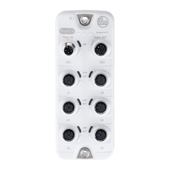
AL3151 Ethernet switch 6 Electrical connection 6.1 Overview XD1: Voltage supply XD2: Voltage output Ethernet port 1 Ethernet port 2 Ethernet port 3 Ethernet port 4 Ethernet port 5 Ethernet port 6 6.2 General wiring information The device must be connected by a qualified electrician. -
Page 9: Voltage Output
Ethernet switch AL3151 u For connection, use M12 connectors (with at least protection rating: IP 65 / IP 66 / IP 67 / IP 69K). Max. cable length: 100 m. u Do not connect the Ethernet ports of the device to each other. This causes a failure of the unit. -
Page 10: Voltage Supply
AL3151 Ethernet switch Connect the device to the mass point (e.g. body, FE of the installation) using the shortest route. 6.6 Voltage supply The device is connected to the supply voltage US via the power IN port. The supply voltage US supplies the device with voltage. -
Page 11: Operating And Display Elements
Ethernet switch AL3151 7 Operating and display elements 7.1 LEDs US (port XD1) LNK / ACT (port X2) LNK / ACT (port X4) LNK / ACT (port X6) LNK / ACT (port X5) LNK / ACT (port X3) LNK / ACT (port X1) 7.1.1 Voltage supply... -
Page 12: Set-Up
AL3151 Ethernet switch 8 Set-up u Install the device correctly. u Establish a correct electrical connection with the device. w Once connected to the supply voltage, the device will start. w The LEDs show the status of the device. w The unit is ready for operation. -
Page 13: Maintenance, Repair And Disposal
Ethernet switch AL3151 9 Maintenance, repair and disposal The operation of the unit is maintenance-free. u Dispose of the device in an environmentally friendly way in accordance with the applicable national regulations when it is no longer used. 9.1 Cleaning the housing surface Clean the surface of the device when necessary.