Table of Contents
Advertisement
Quick Links
Standard Dimming Transceiver Switch
TROUBLESHOOTING
PROBLEM
PROBABLE CAUSE
Master switch is wired
Air gap power disconnect may be disengaged
properly but has no power.
(pulled out).
3-way remote switch actuator may be binding,
Master switch actuator
causing the switch to be stuck ON or OFF.
doesn't turn load ON
Actuator faceplate may not be seated properly
and/or OFF.
on the switch body.
Mounting screws may be too tight or j-box may
Rocker sticks or doesn't
be deformed, causing the switch body to warp.
actuate properly when
Actuator springs may have backed out of their
pressed.
correct location during shipping.
Switch is overloaded.
Switch runs hot when
Switch is dimming a load that is not rated for
dimming the load.
use with incandescent dimmers.
UPB FACTORY DEFAULT SETTINGS
To restore the following default settings, place the US1 in SETUP mode
and tap any actuator exactly 10 times. The indicator will continuously
blink RED. Tap the actuator twice again to exit SETUP mode.
Network Name
"Network 1"
Room Name
"New Room Name"
Device Name
"New SA US1/US2"
Unit ID
22
Network ID
255
Network Password
1234
Transmit Link
1
Receive Links
1 (ON) and 2(OFF)
Model US11-30
SOLUTION
Push light pipe (indicator) back into position flush with faceplate
assembly housing.
Loosen mounting screws on remote switch and/or wallplate to
relieve pressure on housing.
Exercise actuator several times to ensure proper seating and
Loosen mounting screws to relieve pressure on the switch
housing.
Reseat the springs: place the faceplate face-up on a flat surface,
then press down on both sides of each rocker at the same time.
Reduce the power load by removing bulbs from the circuit.
Reconfigure the switch for ON/OFF operation with no dimming
(using UPStart, for example).
POWER DISCONNECTION
To physically disconnect power to the connected lamp fixture, depress
the top of the rocker switch, grab the underside of the clear plastic
indicator tab with your fingernail, pull the tab out about 0.05", then push
the tab down to lock it in place. The indicator will extinguish to show
that power is now disconnected. To reconnect power, simply push the
tab up and it will snap back into its normal position.
Simply Automated, Incorporated
5825 Avenida Encinas, Suite 101, Carlsbad, CA 92008 USA
Technical Support: www.simply-automated.com or 800-630-9234
Revised: August 15, 2005
UPB Standard Dimming Transceiver Switch
Model US11-30
Provides ON/OFF and dimming control for:
•
Incandescent lighting
•
Magnetic low-voltage lighting
•
Halogen lighting
IMPORTANT!
Read This Before Installing!
•
This incandescent dimmer
cannot be used to dim
FLUORESCENT, ELECTRONIC LOW-VOLTAGE or
METAL HALIDE
lighting, unless specifically
allowed by the lighting manufacturer.
Please see
instructions
to configure this product for ON/OFF
operation with these types of lighting.
•
DO NOT WIRE HOT!
Permanent damage may
result. Improper installation voids the warranty.
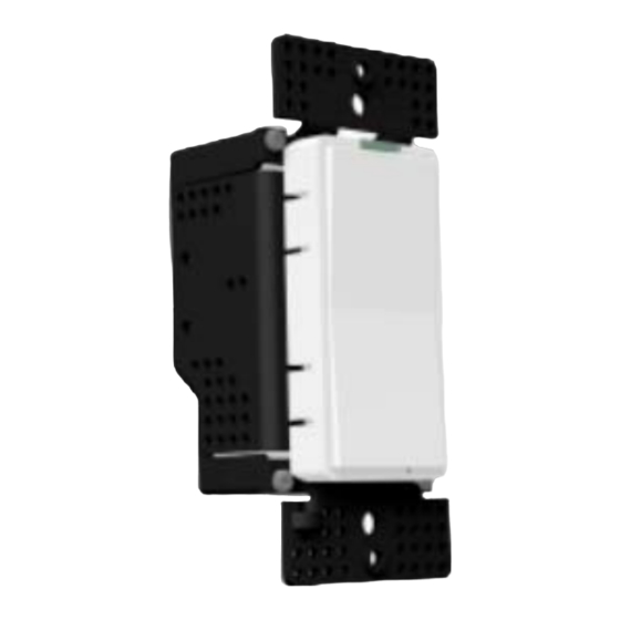
Model US11-30 shown with actuator faceplate
FUNCTION
The SimplyBrilliant™ UPB Dimming Transceiver Switch, model US11-30,
allows remote control of permanently-installed new or existing lighting
fixtures, lamps and other electrical devices. Each unit has one rocker
switch that directly controls a load up to 900W. Incandescent lamps can
be turned ON or OFF, and can also be dimmed and brightened. The
US11-30 can be configured to turn other types of non-dimmable loads ON
and OFF. The switch also acts as a transmitter that can communicate
with other UPB devices, either individually or collectively for lighting
scenes.
IMPORTANT SAFETY INSTRUCTIONS
When using electrical products, basic safety precautions should always
be followed, including the following:
1.
READ AND FOLLOW ALL SAFETY INSTRUCTIONS.
2.
REMOVE YELLOW "INSTALL WITH CARE" LABEL BEFORE
INSTALLING.
3.
Installation should be performed by a qualified electrician.
4.
Keep away from water. If product comes into contact with water or
other liquid, disconnect immediately.
5.
Never use products that have been dropped or damaged.
6.
Do not use this product outdoors.
7.
Do not use this product for other than its intended use.
8.
Do not connect multiple lamps that, when combined, exceed the
maximum load rating of the product, de-rated for multi-gang boxes.
9.
Do not install in areas that can exceed 120°F (e.g., in an attic).
10. To avoid the risk of overheating and possible damage to other
equipment, do not use this product to control a receptacle.
11. Do not cover the product with any material when in use.
12. SAVE THESE INSTRUCTIONS.
INSTALLATION
The SimplyBrilliant™ UPB Dimming Transceiver Switch (US11-30) is
designed to be installed in a junction box that is wired to a readily
accessible over-current protection device in the building wiring per NEC
and CEC electrical codes.
CAUTION: The default switch configuration operates as a dimmer for
incandescent lamps. It will also dim magnetic low-voltage and
halogen lamps. To control fluorescent, electronic low-voltage or
metal halide lamps, or motor-operated appliances, transformer-
supplied appliances or fans, the switch must be reconfigured for
ON/OFF operation (no dimming) prior to use. Refer to the section on
CAUTION: DO NOT WIRE THIS DEVICE WITH POWER
CONNECTED. Injury or permanent damage to the device
may result. Improper installation voids the product warranty.
1.
Locate the existing wall switch for the lighting to be controlled. Note
that the lamp rating (or the combined rating of all connected lamps)
must not exceed what is shown in the de-rating table below.
Number of Load
Dimmers in J-box
1
2
3+
1
600W
--
--
Number
of J-box
2
800W
500W
--
Gangs
3+
900W
700W
500W
2.
Disconnect power at the circuit breaker.
3.
Remove the existing wall switch hardware. Disconnect the wires to
the switch.
4.
Remove the yellow "INSTALL WITH CARE" label, if present.
5.
Using a wire nut, connect the black (Line) wire of the switch to the
black (Line) power wire.
6.
Using a wire nut, connect all white (Neutral) wires together.
7.
Using a wire nut, connect the brown (load output) wire of the US11-
30 to the black wire of the device to be controlled.
8.
IF THIS IS TO BE A 3- OR MORE-WAY INSTALLATION, use a wire
nut to connect the brown/white wire to the traveler wire that extends
to the slave switch. If there is a second slave and a second traveler,
use a wire nut to connect the red/white traveler to the wire that
extends to the second slave switch location. Refer to the wiring
diagrams on pages 3 and 4.
9.
Mount the switch inside the J-box using captive screws. DO NOT
OVER TIGHTEN THE SCREWS.
10. Reconnect power at the circuit breaker.
Simply Automated, Incorporated
5825 Avenida Encinas, Suite 101, Carlsbad, CA 92008 USA
Technical Support: www.simply-automated.com or 800-630-9234
Revised: August 15, 2005
Advertisement
Table of Contents

Related Manuals for Simply Automated SimplyBrilliant US11-30


Summary of Contents for Simply Automated SimplyBrilliant US11-30
- Page 1 Mount the switch inside the J-box using captive screws. DO NOT OVER TIGHTEN THE SCREWS. 10. Reconnect power at the circuit breaker. Simply Automated, Incorporated Simply Automated, Incorporated 5825 Avenida Encinas, Suite 101, Carlsbad, CA 92008 USA 5825 Avenida Encinas, Suite 101, Carlsbad, CA 92008 USA Technical Support: www.simply-automated.com or 800-630-9234...
- Page 2 Standard Dimming Transceiver Switch Model US11-30 Standard Dimming Transceiver Switch Model US11-30 By linking a transmitting switch to a UPB Lamp or Fixture Dimmer Module, the connected load can be controlled according to the REMOTE SWITCH INSTALLATION table above. To install a USR Dedicated Remote switch for 3- or more-way control: INSTALLING/CHANGING FACEPLATES Locate the remote switch that is connected to the master wall switch.
Need help?
Do you have a question about the SimplyBrilliant US11-30 and is the answer not in the manual?
Questions and answers