Table of Contents
Advertisement
Quick Links
SAFETY PRECAUTION FOR SERVICE MANUAL ........................................................................................................... 2
VOLTAGE SELECTION ..................................................................................................................................................... 2
AC POWER SUPPLY CORD AND AC PLUG ADAPTOR ................................................................................................. 3
SPECIFICATIONS ............................................................................................................................................................. 3
NAMES OF PARTS ........................................................................................................................................................... 4
OPERATION MANUAL ...................................................................................................................................................... 6
DISASSEMBLY .................................................................................................................................................................. 9
REMOVING AND REINSTALLING THE MAIN PARTS ................................................................................................... 12
ADJUSTMENT ................................................................................................................................................................. 13
BLOCK DIAGRAM ........................................................................................................................................................... 17
SCHEMATIC DIAGRAM / WIRING SIDE OF P.W.BOARD .............................................................................................. 20
VOLTAGE ........................................................................................................................................................................ 38
NOTES ON SCHEMATIC DIAGRAM .............................................................................................................................. 39
TYPES OF TRANSISTOR AND LED ................................................................................................................................ 39
WAVEFORMS OF CD CIRCUIT ...................................................................................................................................... 40
TROUBLESHOOTING ..................................................................................................................................................... 41
FUNCTION TABLE OF IC ................................................................................................................................................ 45
FL DISPLAY ...................................................................................................................................................................... 53
REPLACEMENT PARTS LIST/EXPLODED VIEW
All manuals and user guides at all-guides.com
SERVICE MANUAL
MODEL
MODEL
CONTENTS
SHARP CORPORATION
- 1 -
CD-M4000W/CP-M4000
MINI COMPONENT SYSTEM
CD-M4000W
SPEAKER SYSTEM
CP-M4000
• In the interests of user-safety the set should be restored to its
original condition and only parts identical to those specified be
used.
This document has been published to be used
for after sales service only.
The contents are subject to change without notice.
No. S9156CDM4000W
Page
Advertisement
Table of Contents

Related Manuals for Sharp CD-M4000W


Summary of Contents for Sharp CD-M4000W
-
Page 1: Table Of Contents
All manuals and user guides at all-guides.com CD-M4000W/CP-M4000 SERVICE MANUAL No. S9156CDM4000W MINI COMPONENT SYSTEM CD-M4000W MODEL SPEAKER SYSTEM CP-M4000 MODEL • In the interests of user-safety the set should be restored to its original condition and only parts identical to those specified be used. -
Page 2: Safety Precaution For Service Manual
All manuals and user guides at all-guides.com CD-M4000W/CP-M4000 SAFETY PRECAUTION FOR SERVICE MANUAL WARNINGS THE AEL (ACCESSIBLE EMISSION LEVEL) OF THE LASER POWER OUTPUT IS LESS THAN CLASS 1 BUT THE LASER COMPONENT IS CAPABLE OF EMITTING RADIATION EXCEEDING THE LIMIT FOR CLASS 1. THEREFORE IT IS IMPORTANT THAT THE FOLLOWING PRECAUTIONS ARE OBSERVED DURING SERVICING TO PROTECT YOUR EYES AGAINST EXPOSURE TO THE LASER BEAM. -
Page 3: Ac Power Supply Cord And Ac Plug Adaptor
All manuals and user guides at all-guides.com CD-M4000W/CP-M4000 AC POWER SUPPLY CORD AND AC PLUG ADAPTOR QACCA0003AW00 QACCL0005AW00 QACCE0008AW00 QPLGA0004AWZZ QPLGA0003AWZZ FOR A COMPLETE DESCRIPTION OF THE OPERATION OF THIS UNIT, PLEASE REFER TO THE OPERATION MANUAL. SPECIFICATIONS CD-M4000W General... -
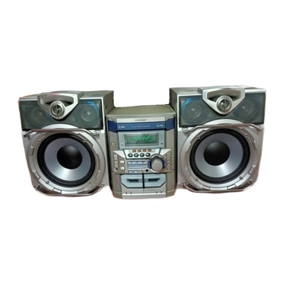
Page 4: Names Of Parts
All manuals and user guides at all-guides.com CD-M4000W/CP-M4000 NAMES OF PARTS CD-M4000W Front panel 1. Disc Tray 2. Timer Set Indicator 3. On/Stand-by Button 4. Tape 2 Cassette Compartment 5. Tape 1 Cassette Compartment 6. Equalizer Mode Select Button 7. Volume Control 8. - Page 5 All manuals and user guides at all-guides.com CD-M4000W/CP-M4000 CD-M4000W Rear panel 1. FM 75 Ohms Aerial Terminal 2. FM Aerial Earth Terminal 3. AM Loop Aerial Socket 4. Span Selector Switch 5. Video/Auxiliary (Audio Signal) Input Sockets 6. Speaker Terminals 7.
-
Page 6: Operation Manual
All manuals and user guides at all-guides.com CD-M4000W/CP-M4000 CP-M4000 Speaker system 1. Tweeter 2. Super Tweeter 3. Midrange 4. Woofer 5. Bass Reflex Duc 6. Speaker Terminals OPERATION MANUAL System Connections Setting the AC voltage selector Setting the FM/AM span selector Check the setting of the AC voltage selector located on the rear panel before plug- ging the unit into a wall socket. - Page 7 All manuals and user guides at all-guides.com CD-M4000W/CP-M4000 Setting the Clock Press the TUNING/TIME ( or ) button to adjust the hour and then press the MEMORY/SET button. Press the TUNING/TIME ( ) button once to advance the time by 1 hour.
- Page 8 Cassette deck nician. If something is wrong with this product, check the following before calling your autho- Symptom Possible cause rised SHARP dealer or service centre. Cannot record. Is the erase-prevention tab removed? General Cannot record tracks with proper Is it a normal tape? (Yo u cannot record on sound quality.
-
Page 9: Disassembly
All manuals and user guides at all-guides.com CD-M4000W/CP-M4000 DISASSEMBLY CD-M4000W Caution on Disassembly Follow the below-mentioned notes when disassembling (A1) x 2 Top Cabinet the unit and reassembling it, to keep it safe and ensure ø3 x 12mm excellent performance: 1. - Page 10 All manuals and user guides at all-guides.com CD-M4000W/CP-M4000 (H1) x 1 (H3) x 1 Clamp Lever Display PWB (L1) x 2 ø3 x 10mm (H2) x 12 ø3 x 10mm Mic PWB CD Player Unit Tape (Top View) Mechanism Front...
- Page 11 All manuals and user guides at all-guides.com CD-M4000W/CP-M4000 (Q2) x 3 Mechanism (P1) x 1 Slide CD Servo ø3 x 8mm Chassis (P3) x 2 Mechanism (Q1) x 1 (Q1) x 1 Chassis (P2) x 2 (P3) x 2 Slide...
-
Page 12: Removing And Reinstalling The Main Parts
All manuals and user guides at all-guides.com CD-M4000W/CP-M4000 REMOVING AND REINSTALLING THE MAIN PARTS TAPE 2 TAPE MECHANISM SECTION Clutch Ass'y Perform steps 1 to 7 and 9 of the disassembly method to Record/Playback remove the tape mechanism. Head How to remove the record/playback and erase heads (TAPE 2) (See Fig. -
Page 13: Adjustment
All manuals and user guides at all-guides.com CD-M4000W/CP-M4000 CD MECHANISM SECTION CD Loading Motor Perform steps 1, 2, 3, 12, 13, 14 and 15 of the disassembly CD Loading Slide method to remove the CD mechanism. Motor PWB Chassis How to remove the CD loading motor (See Fig. - Page 14 All manuals and user guides at all-guides.com CD-M4000W/CP-M4000 • FM RF TUNER SECTION Signal generator: 1 kHz, 40 kHz dev., FM modulated fL: Low-range frequency fH: High-range frequency Test Stage Frequency Frequency Setting/ Instrument Display Adjusting • AM IF/RF Connection...
- Page 15 All manuals and user guides at all-guides.com CD-M4000W/CP-M4000 TEST MODE • Setting the test mode Any one of test mode can be set by pressing several keys as follows. <X-BASS> + <CD> + <POWER> TEST:CD operation test Function:-CD test mode.
- Page 16 All manuals and user guides at all-guides.com CD-M4000W/CP-M4000 Standard Specification of Stereo System Error Message Display Contents Error Contents Display Notes Output while Device Protection Operation 'PROTECT' 00: While in Protect Circuit Operate 01: Over Current Detection 02: DC Detection...
-
Page 17: Block Diagram
All manuals and user guides at all-guides.com CD-M4000W/CP-M4000 DISC CLAMP NUMBER OPEN/ CLOSE CD LOADING TO MAIN SECTION TO DISPLAY SECTION 43 44 VWRQ VRES LC78645E CD SERVO XOUT 17 25 CONT5 SLDO SPDO VCC1 M63001FP VCC4 FOCUS/TRACKING/ VCC2 SPIN/SLED +3.3V... - Page 18 All manuals and user guides at all-guides.com CD-M4000W/CP-M4000 ANTENNA TERMINAL FM IF 10.7MHz SO301 IC301 T302 CF303 X351 TA7358AP BF301 456kHz CF351 FM FRONT END 450kHz B.P.F MO/ST T351 CF352 AM IF 17 13 IC303 AM MIX AM IF LA1832S...
- Page 19 All manuals and user guides at all-guides.com CD-M4000W/CP-M4000 FL701 FL DISPLAY JOG701 14 16 33 44 56 57 58 VOLUME Q701-Q703 RX701 REMOTE SENSOR SW701-SW703 SW709-SW717 VLOAD SW722-SW734 IC701(1/2) IC702 BU2092F IX0460AW AVDD INPUT/OUTPUT SYSTEM MICROCOMPUTER EXPANDER IC702 9 10 11 12 13 15 16 17...
-
Page 20: Schematic Diagram / Wiring Side Of P.w.board
All manuals and user guides at all-guides.com CD-M4000W/CP-M4000 PICKUP UNIT CD SERVO PWB-C CD SIGNAL VREF VREF LASER DRIVER 8.2K 8.2K 0.047(ML) CNP1 0.0047 (CH) 10/50 0.001 0.001 100/10 TR– TR– 0.22/50 FO– FO– 100P FO– TR– 0.01 CNP2 100/10... - Page 21 All manuals and user guides at all-guides.com CD-M4000W/CP-M4000 R38 1K 100P R37 1K 100P R36 1K 100P R35 1K R34 1K 100P R33 1K R32 1K 100P 0.022 CNS703 2.2K FROM CD RES DISPLAY PWB P25 12-A CLAMP SW 47(ML) 2.2K...
- Page 22 All manuals and user guides at all-guides.com CD-M4000W/CP-M4000 IC601 C606 LC75341 100/16 C602 AUDIO PROCESSOR VREF 22/25 + – C607 0.22(ML) INTERFACE C609 LOUT ROUT 0.22(ML) C610 0.22(ML) RBASS R605 LBASS C613 3.9K 10/50 C611 RTRE C619 LTRE C620 0.0015...
- Page 23 All manuals and user guides at all-guides.com CD-M4000W/CP-M4000 MAIN PWB-A(1/2) FM SIGNAL PLAYBACK SIGNAL RECORD SIGNAL CD SIGNAL C602 VIDEO SIGNAL VREF 22/25 C614 R608 MIC SIGNAL 10/50 R633 ROUT C610 R606 L-CH 0.22(ML) C608 3.9K C631 R631 0.22 390P RBASS 8.2K...
- Page 24 All manuals and user guides at all-guides.com CD-M4000W/CP-M4000 DISPLAY PWB-B1 FL701 FL DISPLAY R701 R704 R716 100K 100K 100K Q701 Q702 Q703 KTC3199 GR C715 KTC3199 GR KTC3199 GR 22/50 C714 47/50 VLOAD R727 R728 DT701 DS1SS133 P19/DIST0 R794 P20/DIST1...
- Page 25 All manuals and user guides at all-guides.com CD-M4000W/CP-M4000 CD SERVO PWB P21 12-B CNP8 CNS703 C722 47/50 2 3 4 BI703 C726 220/10 CNS705 R773 C725 -20dBATT 0.022 DSA_STB R775 T-BIAS R776 P_IN T-T1/T2 R777 BI705 REC/PLAY R778 RES OUT...
- Page 26 All manuals and user guides at all-guides.com CD-M4000W/CP-M4000 IC901 – STK41203 POWER AMP C911 Q903 KTC3199 R912 (1/4W) D909 Fusible C915 R918 DS1SS133 ZD902 ZD901 47/50 0.1(3W) DZ12BSB DZ12BSB C916 47/50 C921 C924 R951 R920 R952 100/50 0.022 3.9K 1.5K 3.9K...
- Page 27 All manuals and user guides at all-guides.com CD-M4000W/CP-M4000 AMP. PWB-D2 FM SIGNAL R945 R947 (1/2W) (1/2W) C931 C935 0.022 (ML) C937 C933 RL901 L901 0.022 0.29µH (ML) R-CH Q903 R925 KTC3199 GR 10 (1/2W) C927 SO901 D909 SPEAKER (ML) DS1SS133...
- Page 28 All manuals and user guides at all-guides.com CD-M4000W/CP-M4000 AM LOOP ANTENNA SO301 FM ANTENNA CNP301 TERMINAL MAIN PWB-A (2/2) BF301 C314 B.P.F. D305 DS1SS133 0.0047 C303 C308 4.7P(CH) 10P(CH) FM RF C304 L312 IC301 0.01 C315 0.0047 C309 TA7358AP R311 100K 0.001...
- Page 29 All manuals and user guides at all-guides.com CD-M4000W/CP-M4000 MIC PWB-H MIC SIGNAL CK48 220P RK47 CK41 8.2K CK53 100/16 47/50 RK46 ICK1 DS1SS133 CK50 M65856SP CK46 100P MIC AMP. 2.2/50 RK45 RK11 6.8K DATA MICSW DS1SS133 CK35 0.01 CK51 RK10...
- Page 30 All manuals and user guides at all-guides.com CD-M4000W/CP-M4000 TO MIC PWB TO CD SERVO PWB P29 12-G P36 5-A CNPK1 CNP7 CNS602 CNS11 1 2 3 4 5 6 1 2 3 4 5 6 8 9 10 MAIN PWB-A...
- Page 31 All manuals and user guides at all-guides.com CD-M4000W/CP-M4000 TO DISPLAY PWB P33 11-A CNP701 FC701 Q122 R156 B C E C146 R140 R158 R146 C142 R132 R154 C140 C124 C135 R153 C145 R142 Q121 R145 C136 C141 B C E...
- Page 32 All manuals and user guides at all-guides.com CD-M4000W/CP-M4000 DISPLAY PWB-B1 1 2 3 6 7 8 9 10 11 12 13 14 15 16 CNS703 BI703 R702 C722 CNP8 R705 Q701 Q703 R719 TO CD SERVO PWB P36 4-A R796...
- Page 33 All manuals and user guides at all-guides.com CD-M4000W/CP-M4000 TO MAIN PWB P31 9-A CNP601 FC701 25 26 27 28 29 30 31 32 33 34 35 36 37 38 39 40 41 42 43 44 56 57 58 R727 FL701...
- Page 34 All manuals and user guides at all-guides.com CD-M4000W/CP-M4000 TRANSFORMER PWB-D3 AC POWER SUPPLY CORD AC 110/127/220/ 230-240 V, 50/60 Hz 230-240V 220V SW801 VOLTAGE SELECTOR COLOR TABLE 127V 110V BROWN RD(R) ORANGE LG801 LG802 YELLOW GREEN BLUE VIOLET GRAY WH(W)
- Page 35 All manuals and user guides at all-guides.com CD-M4000W/CP-M4000 SO901 SPEAKER TERMINAL L-CH R-CH AMP. PWB-D2 R948 LG901 R947 Q907 R933 CNP904 RL901 C937 B C E R946 R939 C936 C935 R938 R945 C931 C938 Q905 D912 C932 1 2 3...
- Page 36 All manuals and user guides at all-guides.com CD-M4000W/CP-M4000 P30 4-A P32 1-B FROM DISPLAY PWB FROM MAIN PWB CD SERVO PWB-C CNS11 CNP703 1 2 3 4 5 6 7 8 9 1 2 3 4 5 6 CNP7 CNP8...
- Page 37 All manuals and user guides at all-guides.com CD-M4000W/CP-M4000 P32 4-B TAPE MECHANISM TO DISPLAY PWB ASSEMBLY CNS703 FC702 TAPE MECHANISM PWB-F SOLENOID SOLENOID TAPE MOTOR TAPE 1 PLAYBACK HEAD TAPE 2 RECORD/PLAYBACK/ERASE HEAD 654321 CNS102 P31 12-D CNP101 FROM MAIN PWB...
-
Page 38: Voltage
All manuals and user guides at all-guides.com CD-M4000W/CP-M4000 VOLTAGE IC101 IC601 IC701 NO. VOLTAGE NO. VOLTAGE NO. VOLTAGE NO. VOLTAGE NO. VOLTAGE NO. VOLTAGE 1.6 V 3.7 V 4.23 V 3.7 V 4.14 V 1.6 V 0.5 V 4.6 V 1.8 V... -
Page 39: Notes On Schematic Diagram
All manuals and user guides at all-guides.com CD-M4000W/CP-M4000 NOTES ON SCHEMATIC DIAGRAM • Resistor: • The indicated voltage in each section is the one measured by Digital Multimeter between such a section and the chas- To differentiate the units of resistors, such symbol as K and M are used: the symbol K means 1000 ohm and the symbol sis with no signal given. -
Page 40: Waveforms Of Cd Circuit
All manuals and user guides at all-guides.com CD-M4000W/CP-M4000 WAVEFORMS OF CD CIRCUIT Stopped Stopped 1999/04/07 09:51:15 CH1=200 mV CH2=500 mV 500 ms/div CH1=500 mV CH3=500 mV 500 ms/div DC 10:1 DC 10:1 (500 ms/div) (500 ms/div) DC 10:1 DC 10:1... -
Page 41: Troubleshooting
All manuals and user guides at all-guides.com CD-M4000W/CP-M4000 TROUBLESHOOTING When the CD does not function When the CD section does not operate when the objective lens of the optical pickup is dirty, this section may not operate. Clean the objective lens, and check the playback operation. When this section does not operate even after the above step is taken, check the following items. - Page 42 All manuals and user guides at all-guides.com CD-M4000W/CP-M4000 Stopped (1) Focus-HF system check. CH1=500 mV CH3=500 mV 500 ms/div DC 10:1 DC 10:1 (500 ms/div) NORM:20 kS/s Although a CD is inserted and the cover is closed, "NO DISC" is displayed.
- Page 43 All manuals and user guides at all-guides.com CD-M4000W/CP-M4000 (2) Tracking system check. Check the TE waveform at pin 15 on IC1. The tracking servo is not activated. If the waveform shown in Figure 43-1 appears and soon after Check the peripheral circuits at pins 14, 15 and 20 on IC1, and NO DISC appears ? CNS1A/B.
- Page 44 All manuals and user guides at all-guides.com CD-M4000W/CP-M4000 (4) PLL system check. Stopped 1999/04/05 17:33:17 CH1=500 mV CH3=1 V CH4=1 V 500 ms/div DC 10:1 DC 10:1 DC 10:1 (500 ms/div) NORM:20 kS/s When a disc is loaded, start play operation.
-
Page 45: Function Table Of Ic
All manuals and user guides at all-guides.com CD-M4000W/CP-M4000 FUNCTION TABLE OF IC IC1 VHiLC78645E-1: CD Servo (LC78645E) (1/2) Terminal Name Input/Output Setting in Reset Function Pin No. SLCO Output — Control output. For slice level SLCIST Input — Resistor connection terminal for SLCO output current setting. - Page 46 All manuals and user guides at all-guides.com CD-M4000W/CP-M4000 IC1 VHiLC78645E-1: CD Servo (LC78645E) (2/2) Terminal Name Input/Output Setting in Reset Pin No. Function RVSS — — GND for Right channel. Must be connected to 0 V. Right channel RCHO Output LVDD /2 Right channel output.
- Page 47 All manuals and user guides at all-guides.com CD-M4000W/CP-M4000 IC1 VHiLC78645E-1: CD Servo (LC78645E) 75 74 72 71 69 68 66 65 63 62 SLC0 DATA SLCIST DATACK EFMIN LRSY ASDFIN RFVDD ASDACK RFVSS ASLRCK FIN1 16MOUT FIN2 EFLG TIN1 TIN2...
- Page 48 All manuals and user guides at all-guides.com CD-M4000W/CP-M4000 IC701 RH-iX0460AWZZ: System Microcomputer (IX0460AW) (1/2) Pin No. Port Name Terminal Name Input/Output Function Input (+) Power supply. -20 dB ATT Output -20 dB attenuator. NO USE Output DSA_STB Input/Output DSA strube...
- Page 49 All manuals and user guides at all-guides.com CD-M4000W/CP-M4000 IC701 RH-iX0460AWZZ: System Microcomputer (IX0460AW) (2/2) Pin No. Port Name Terminal Name Input/Output Function P124 T 1 RUN Input Tape 1 run pulse imput. P123 T 2 RUN Input Tape 2 run pulse input.
- Page 50 All manuals and user guides at all-guides.com CD-M4000W/CP-M4000 IC601 VHiLC75341/-1: Audio Processor (LC75341) ROUT LOUT LBASS RBASS 0.1uF 0.1uF LTRE RTRE LSEL0 RSEL0 R1 R2 24 23 22 21 20 19 18 17 16 15 14 13 LC75341 10 11 12 Figure 50 BLOCK DIAGRAM OF IC –...
- Page 51 All manuals and user guides at all-guides.com CD-M4000W/CP-M4000 ICK1 VHiM65856SP-1: Mic Amp. (M65856SP) (1/2) Pin No. Port Name Input/Output Function MIC SW Input Microphone SW L: MIC OFF, H: MIC ON MCLKCONT — Clock Control. Controls built-in clock generation circuit with external R.
- Page 52 All manuals and user guides at all-guides.com CD-M4000W/CP-M4000 ICK1 VHiM65856SP-1: Mic Amp. (M65856SP) (2/2) Pin No. Port Name Input/Output Function KEYCONIN Input Monaural input for external KEYCONTROL IC. Input/Output interface terminal for external KEYCONTROL IC. SOURCEOUT Output Monaural input for external KEYCONTROL IC.
-
Page 53: Fl Display
All manuals and user guides at all-guides.com CD-M4000W/CP-M4000 FL DISPLAY FL701 VVKBJ11LM02T1: FL Display B7 B6 B5 B4 B3 B3 B4 B5 B6 B7 (Hiper) (Lower) – 53 –... - Page 54 All manuals and user guides at all-guides.com CD-M4000W/CP-M4000 –– MEMO –– – 54 –...
- Page 55 “HOW TO ORDER REPLACEMENT PARTS” To have your order filled promptly and correctly, please furnish the For U.S.A. only following information. Contact your nearest SHARP Parts Distributor to order. 1. MODEL NUMBER 2. REF. No. 3. PART NO. 4. DESCRIPTION For location of SHARP Parts Distributor, Please call Toll-Free;...
- Page 56 All manuals and user guides at all-guides.com CD-M4000W/CP-M4000 PRICE PRICE PARTS CODE DESCRIPTION PARTS CODE DESCRIPTION RANK RANK LED722 VHP4204SRT7-1 AD LED,Red,4204SRT7 CD-M4000W VHEDZ3R3BSB-1 AB Zener,3.3V,DZ3.3BSB VHEDZ3R9BSB-1 AC Zener,3.9V,DZ3.9BSB INTEGRATED CIRCUITS ZD351 VHEDZ5R1BSB-1 AC Zener,5.1V,DZ5.1BSB ZD701 VHEMTZJ6R2C-1 AC Zener,6.2V,MTZJ6.2C VHILC78645E-1...
- Page 57 All manuals and user guides at all-guides.com CD-M4000W/CP-M4000 PRICE PRICE DESCRIPTION PARTS CODE DESCRIPTION PARTS CODE RANK RANK AB 100 µF,10V,Electrolytic AA 0.022 µF,25V VCEAZA1AW107M J C395 VCTYMN1EF223Z AA 0.01 µF,16V AB 100 µF,10V,Electrolytic VCTYMN1CY103N J C396 VCEAZA1AW107M J AA 0.001 µF,50V AA 0.022 µF,25V...
- Page 58 All manuals and user guides at all-guides.com CD-M4000W/CP-M4000 PRICE PRICE PARTS CODE DESCRIPTION PARTS CODE DESCRIPTION RANK RANK AA 0.0047 µF,16V CK13 VCTYPA1CX472K R131,132 VRD-MN2BD123J AA 12 kohms,1/8W AA 0.001 µF,16V CK14 VCTYPA1CX102K R134 VRD-MN2BD683J AA 68 kohms,1/8W AB 0.068 µF,50V,Polyester...
- Page 59 All manuals and user guides at all-guides.com CD-M4000W/CP-M4000 PRICE PRICE DESCRIPTION PARTS CODE DESCRIPTION PARTS CODE RANK RANK R706 VRD-ST2CD103J AA 10 kohm,1/6W R940 VRD-RT2HD221J AA 220 kohms,1/2W R708 VRD-ST2CD103J AA 10 kohm,1/6W R941,942 VRS-VV3DA561J AC 560 ohms,2W R713,714 VRD-MN2BD103J...
- Page 60 All manuals and user guides at all-guides.com CD-M4000W/CP-M4000 PRICE PRICE PARTS CODE DESCRIPTION PARTS CODE DESCRIPTION RANK RANK BI102/CNS102 QCNWN1974AWZZ J AM Connector Ass’y,7/6Pin SW728 92LSWICHT1663T J AC Switch,Key Type [Play] BI602/CNS602 QCNWN1876AWZZ J AH Connector Ass’y,10/10Pin SW729 92LSWICHT1663T J...
- Page 61 All manuals and user guides at all-guides.com CD-M4000W/CP-M4000 PRICE PRICE DESCRIPTION PARTS CODE DESCRIPTION PARTS CODE RANK RANK GITAR0855AWSA Rear Panel [For Russia] XESSD30P10000 AA Screw,ø3×10mm LANGK0057AWFW J AE Bracket,Main Heat Sink [Left] XHBSD30P06000 AA Screw,ø3×6mm LANGK0058AWFW J AE Bracket,Main Heat Sink [Right] XJBSD30P10000 AA Screw,ø3×10mm...
- Page 62 All manuals and user guides at all-guides.com CD-M4000W/CP-M4000 PRICE PRICE PARTS CODE DESCRIPTION PARTS CODE DESCRIPTION RANK RANK CP-M4000 SPEAKER BOX PARTS HPNLS1035AWSA J Front Panel,Left HPNLS1034AWSA J Front Panel,Right CWAKP1053AWSA J Net Ass'y GBOXS4007AWSA J Speaker Box Ass'y,Left GBOXS2007AWSA J...
- Page 63 All manuals and user guides at all-guides.com CD-M4000W/CP-M4000 CD-M4000W 306-2 306-1 306-3 703x2 305x2 PWB-G Figure 8 CD MECHANISM EXPLODED VIEW – 8 –...
- Page 64 All manuals and user guides at all-guides.com CD-M4000W/CP-M4000 CD-M4000W BELT CONNECTION 603x2 610x11 202-1 FF/REW FF/REW Tape ROLLER ROLLER Motor ASS'Y ASS'Y 610x2 FLYWHEEL FLYWHEEL 612x2 ASS'Y ASS'Y MAIN BELT TAPE1 TAPE2 M901 610x3 Q852 610x2 Q851 Q850 PWB-A 605x2...
- Page 65 All manuals and user guides at all-guides.com CD-M4000W/CP-M4000 CD-M4000W 607x2 607x2 231-1 231-2 MECHANISM 231-3 231-4 231-5 PWB-E PWB-E 243x4 PWB-C 232x4 Figure 10 CABINET EXPLODED VIEW (2/2) – 10 –...
- Page 66 All manuals and user guides at all-guides.com CD-M4000W/CP-M4000 CP-M4000 921x2 921x2 923x2 SP7,8 911x4 922x2 920x4 922x4 910x2 SP1,2 920x4 922x4 SP5,6 922x4 909-2 909-1 (C1,2) 909-4 910x2 SP3,4 SP1,2 (C3,4) 909-3 WOOFER (with Capacitor) SP3,4 SP5,6 MIDRANGE TWEETER SP7,8...
- Page 67 All manuals and user guides at all-guides.com CD-M4000W/CP-M4000 –– MEMO –– – 12 –...
- Page 68 All manuals and user guides at all-guides.com CD-M4000W/CP-M4000 © COPYRIGHT 2001 BY SHARP CORPORATION ALL RIGHTS RESERVED. No part of this publication may be reproduced, stored in a retrieval system, or transmitted in any form or by any means, electronic, mechanical, photocopying, recording, or otherwise, without prior written permission of the publisher.
Need help?
Do you have a question about the CD-M4000W and is the answer not in the manual?
Questions and answers