Table of Contents
Advertisement
Quick Links
®
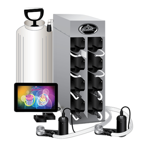
Flavor Burst
Frozen Beverage System
Model TS 44SS/BEV
Manufactured by
Flavor Burst Company
499 Commerce Drive
Danville, IN 46122
For general information and to locate a
distributor near you, call or visit our website:
Phone: (317) 745-2952
Toll Free Number: (800) 264-3528
Fax: (317) 745-2377
www.flavorburst.com
For pricing, ordering and support, contact one
of our qualified distributors.
Warranty
An installation and warranty form is provided with every TS 44SS/BEV system, located inside the
TS 44SS/BEV unit with this manual. It is important that the operator carefully review the warranty and
installation documents accompanying the unit before using this system. Any questions or concerns
regarding the warranty should be clarified upon delivery or installation. For more information, contact
®
your local authorized Flavor Burst
distributor.
©2014 Flavor Burst Company
Printed in January
Printed in
All Rights Reserved
The United States of America
Advertisement
Table of Contents

Subscribe to Our Youtube Channel
Summary of Contents for Flavor Burst TS 44SS/BEV
- Page 1 An installation and warranty form is provided with every TS 44SS/BEV system, located inside the TS 44SS/BEV unit with this manual. It is important that the operator carefully review the warranty and installation documents accompanying the unit before using this system. Any questions or concerns regarding the warranty should be clarified upon delivery or installation.
-
Page 2: Table Of Contents
TABLE OF CONTENTS Safety Precautions and Procedure Notes….…………….………..……..….…………..3 Introduction……………………………...………………………………………….………….4 Parts Identification/Function……...……………………….……..…..……….……..….…..5 Daily Opening Procedures……..………………………….…….…..…….………..……...30 Sanitizing the Injector / Blending System…………………….……………...…...…30 Assembling the Injector / Blending Assembly……...………………...………..…31 Installing the Injector / Blending System……………………………………….……31 Other items to check during opening procedures……………………………….…32 Daily Closing Procedures………………………………………….……………….………34 Removing the Injector / Blending System………………………...…………..…...34 Disassembling the Injector / Blending Assembly…………………………..……35 Sanitizing the Injector / Blending System……………………..…………..…..35... - Page 3 Power Connections and Power Up……………………………………….…..…75 Installing Flavors and Priming Syrup Lines………………………...……….…...…76 Touchscreen Operations…………...…….……………………………………..……...…78 Calibrating the Touchscreen……………..….…………………………………….…78 Enabling the TS 44SS/BEV System….…………………………………………...…79 Testing the TS 44SS/BEV System…………..…………………..……………...…82 Draw Modes Options….………………………………………………………...…….83 Enabling the Standard Manual Draw Mode…………......…83 Dispensing Product – Standard Manual Draw Mode……………….…..…84 Enabling the Timed Serving Size Draw Mode………..…………………..85...
-
Page 4: Safety Precautions And Procedure Notes
The TS 44SS/BEV cabinet system must NOTE: Your hands should be cleaned and be placed on a level surface capable of sanitized before you perform these procedures. -
Page 5: Introduction
We urge you to follow these instructions carefully and maintain strict sanitary practices in your daily operating routine. The TS 44SS/BEV series unit is an add-on system that flavors both a soft-serve freezer barrel and a frozen beverage freezer barrel, blending concentrated flavorings throughout the base product as it is dispensed. -
Page 6: Parts Identification/Function
General System Overview (See Figure 1) ITEM PART NO. DESCRIPTION QTY. FUNCTION TOUCHSCREEN ASSEMBLY Flavor Burst unit command center. 805SS/BEV ELE 434 POWER CABLE Supplies the electronics board with power. INJ 424VTS VERTICAL BLENDING ASSEMBLY Injects syrups into the product. - Page 7 General System Overview Figure 1...
- Page 8 Cabinet – (See Figure 2) ITEM PART NO. DESCRIPTION QTY. FUNCTION ELECTRONICS SYSTEM Houses microprocessor and electronics. Holds tray support brackets and panel CAB 135R-A RIGHT SIDE PANEL brackets. CAB 145 TRAY SUPPORT BRACKET Supports flavoring trays. Fastens panel brackets to divider panel, FAS 2024 8-32 X 1/4 PAN HEAD secures sides.
- Page 9 Cabinet (Continued) ITEM PART NO. DESCRIPTION QTY. FUNCTION MIS 3074 SHORTY PLUG #1672 Covers screw hole in rubber bumper. FAS 2040 6-32 X 1/4" TAPPING SCREW Secures tray support bracket to side panels. CAB 135L-A LEFT SIDE PANEL Holds support brackets and panel brackets. PERISTALTIC SYRUP PUMP –...
- Page 10 Injector Assembly and Related Parts (See Figure 3) ITEM PART NO. DESCRIPTION QTY. FUNCTION INJECTOR ASSEMBLY WITH SYRUP INJ 424TS Transports and blends syrup into product. LINES, ADAPTER, & BRACKET Connects flavor line to inject syrups into INJ 422 INJECTOR HEAD ASSEMBLY product.
- Page 11 Injector Assembly and Related Parts (Continued) ITEM PART NO. DESCRIPTION QTY. FUNCTION CROWN ADAPTER WITH ADPT 8750-A Attaches Injector Assembly to freezer door. O-RINGS Creates tension to secure adapter to freezer RUB 659 TAYLOR ADAPTER O-RING 8750 1 ea. door. CROWN ADAPTER WITOUT ADPT 8750 1 ea.
- Page 12 PAGE INTENTIONALLY LEFT BLANK...
- Page 13 Injector Assembly and Related Parts Figure 3...
- Page 14 Blending Assembly and Related Parts (See Figure 4) ITEM PART NO. DESCRIPTION QTY. FUNCTION VERTICAL BLENDING ASSEMBLY INJ 424VTS WITH SYRUP LINES, ADAPTER, & Transports and blends syrup into product. BRACKET BLENDING HEAD ASSEMBLY – Connects flavor line to inject syrups into INJ 422VS VERTICAL SHAKE product.
- Page 15 Blending Assembly and Related Parts (Continued) ITEM PART NO. DESCRIPTION QTY. FUNCTION INJ 323TS BLENDING ASSEMBLY - NO HEAD Powers Blending system. INJ 330TS BLENDING MOTOR ASSEMBLY 1 ea. Supplies power to Motor which turns gears. Gears turn Gear Cartridge for even syrup INJ 331 BLENDING GEARBOX ASSEMBLY 1 ea.
- Page 16 PAGE INTENTIONALLY LEFT BLANK...
- Page 17 Blending Assembly and Related Parts Figure 4...
- Page 18 Syrup Pump and Related Parts – Soft Serve (See Figure 5) ITEM PART NO. DESCRIPTION QTY. FUNCTION Pumps syrup from flavor bags to flavor SOFT SERVE SYRUP PUMP lines. PERISTALTIC SYRUP PUMP – Pumps syrup from flavor bags to flavor SYR 307 1 ea.
- Page 19 Syrup Pump and Related Parts – Soft Serve Figure 5...
- Page 20 Syrup Pump and Related Parts – Frozen Beverage (See Figure 6) ITEM PART NO. DESCRIPTION QTY. FUNCTION Pumps syrup from flavor bags to flavor SHAKE SYRUP PUMP lines. PERISTALTIC SYRUP PUMP - Pumps syrup from flavor bags into flavor SYR 926 SHAKE EACH lines.
- Page 21 Syrup Pump and Related Parts – Frozen Beverage Figure 6...
- Page 22 Sanitizer Pump and Related Parts (See Figure 7) ITEM PART NO. DESCRIPTION QTY. FUNCTION SAN 748 SANITIZER PUMP ASSEMBLY Supplies sanitizer to flush tube. TUB 807 SANITIZER TUBE REPLACEMENT Transports sanitizer through pump. MIS 3023 DUST CAP Cover to protect end of flavor lines. Creates tension for tighter fit 1 per FAS 2051 ROLLED FLANGE EYELET...
- Page 23 Sanitizer Pump and Related Parts Figure 7...
- Page 24 1 ea. Activates “B” rotor and switch connections. ELE 803 CONNECTOR ELE 805 TOUCHSCREEN SUB-ASSEMBLY 1 ea. Control center for the Flavor Burst system. MALE TO MALE 48” SWITCH EXTENSION ELE 525M 1 ea. Connects Touchscreen to the freezer switch. TOUCHSCREEN CONTROLLER CABLE 1 ea.
- Page 25 Electronic Parts and Connections (Continued) ITEM PART NO. DESCRIPTION QTY. FUNCTION ELE 806 POWER SUPPLY Main power supply. FAS 2024 8-32 X 1/4 PAN HEAD SCREW Secures power supply to the base panel. MIS 3166 CLOSURE PLUG Closes up extra openings. FAS 2008 4-40 X 3/8"...
- Page 26 Spare Parts Kit – Soft Serve (See Figure 9) ITEM PART NO. DESCRIPTION QTY. FUNCTION Houses extra spare parts and wear SPR 5800A SPARE PARTS KIT – SOFT SERVE items. Rotates product for even syrup INJ 321 GEAR CARTRIDGE distribution. Provides sealed cavity and prevents RUB 601 9-POS DUCKBILL CHECK VALVE...
- Page 27 Spare Parts Kit – Soft Serve Figure 9...
- Page 28 Spare Parts Kit – Frozen Beverage (See Figure 10) ITEM PART NO. DESCRIPTION QTY. FUNCTION SPARE PARTS KIT – TOUCHSCREEN Houses extra spare parts and wear items. 5800BEV BEVERAGE Provided to attach switch to freezer or mount MIS 3076 ADHESIVE PAD brackets.
- Page 29 Spare Parts Kit – Frozen Beverage Figure 10...
- Page 30 PAGE INTENTIONALLY LEFT BLANK...
-
Page 31: Daily Opening Procedures
4. Remove the Manifold cap and set it on a DAILY OPENING PROCEDURES sanitary tray. Spray the Syrup Line Manifold opening with approved sanitizer NOTE: PERFORM THE FOLLOWING solution and allow it to sanitize for at least 1 PROCEDURES FOR EACH INJECTOR AND minute. -
Page 32: Assembling The Injector / Blending Assembly
Assembling the Injector / Blending Installing the Injector / Blending System Assembly NOTE: ENSURE THE CORRECT INJECTOR / NOTE: ENSURE THE CORRECT HEAD AND BLENDING HEAD AND GEAR CARTRIDGE GEAR CARTRIDGE ARE INSTALLED ARE INSTALLED TOGETHER AND ON THE TOGETHER. CORRECT FREEZER. -
Page 33: Other Items To Check During Opening Procedures
These steps do not necessarily need to be performed as part of the daily opening procedures. The following is a list of areas to ® check on the Flavor Burst system during opening procedures. These areas should be checked and adjusted if necessary. - Page 34 PAGE INTENTIONALLY LEFT BLANK...
-
Page 35: Daily Closing Procedures
DAILY CLOSING PROCEDURES 3. Disconnect the Drive Motor cable from the Drive Motor. NOTE: PERFORM THE FOLLOWING PROCEDURES FOR EACH INJECTOR AND BLENDING ASSEMBLY. NOTE: PROCEDURES AND INSTRUCTIONS MAY APPLY TO FROZEN BEVERAGE PARTS, FREEZERS AND FITMENTS EVEN WHEN ILLUSTRATIONS SHOW ONLY SOFT SERVE PARTS, FREEZERS AND FITMENTS. -
Page 36: Disassembling The Injector / Blending Assembly
Disassembling the Injector / Blending Sanitizing the Injector / Blending System Assembly 1. Mix approved detergent with warm water according to manufacturer’s instructions. 1. Rotate the Drive Motor to unlock and remove the Drive Motor from the Drive Also prepare approved sanitizer solution according to manufacturer’s instructions. - Page 37 5. When the Drive Assembly Gear Box has 8. Spray the Syrup Line Manifold opening with soaked for at least 5 minutes, brush and approved sanitizer solution. Allow it to clean all exposed surfaces and openings sanitize for at least 1 minute. with detergent water and rinse thoroughly.
- Page 38 12. The following do not need to be sanitized on a daily basis. However, inspect these areas and if necessary, clean according to instructions in the SCHEDULED MAINTENANCE section: 9-Tube Assembly Coupler 9-Tube Assembly Tubes Spout Adapter (clean according to instructions when freezer door has been removed)
-
Page 39: Replacing The Syrup Flavors
REPLACING THE SYRUP FLAVORS 4. For soft serve syrups (trays 1-4): Complete Steps 9-24 of the “CIP – Phase NOTE: USE ONLY SOFT SERVE SYRUPS IN 2A” Clean-In-Place procedure in the TRAYS 1-4 AND ONLY FROZEN BEVERAGE SCHEDULED MAINTENANCE section to SYRUPS IN TRAYS 5-8. - Page 40 11. Make sure the syrup bag is settled neatly 8. Lifting up with the bag fitment, press the into the tray, and then install the loaded tray center pin of the bag fitment valve and into the cabinet. gently press on the bag to release any excess air.
- Page 41 14. Using a spray bottle of approved sanitizer 17. Connect the Syrup Bag Connector to the solution, spray the syrup bag fitment and syrup bag fitment. the Syrup Bag Connector. Allow these parts to sanitize for at least 1 minute. 18.
- Page 42 21. Press the PRIME SYRUP PUMP key. 24. Once syrup flows consistently from the Injector / Blending Head, press the flavor key again to complete the procedure. 25. Press DONE to exit the Prime Syrup Pump mode and return to the main screen. 22.
-
Page 43: Scheduled Maintenance
3. Remove each Coupler Body by rotating and SCHEDULED MAINTENANCE unlocking them from the Coupler Bases. NOTE: THE FOLLOWING PROCEDURES ARE PERFORMED LESS FREQUENTLY THAN DAILY OR AS NEEDED. NOTE: PROCEDURES AND INSTRUCTIONS MAY APPLY TO FROZEN BEVERAGE PARTS, FREEZERS AND FITMENTS EVEN WHEN ILLUSTRATIONS SHOW ONLY SOFT SERVE PARTS, FREEZERS AND FITMENTS. -
Page 44: Cip - Phase 2A: Soft Serve Syrup System Cleaning
6. Clean the Syrup Line Manifolds, Manifold CIP - Phase 2A: Soft Serve Syrup System caps, Duckbill Check Valves, and Coupler Cleaning Bodies using a small brush and detergent water. Be sure that each of the 9 individual NOTE: THE FOLLOWING CLEAN-IN-PLACE check valves is cleaned thoroughly by PROCEDURE (STEPS 8-30) SHOULD BE brushing through each valve opening. - Page 45 11. Place a container on level with or below the 15. Remove the Adapter from the sanitizer sanitizer tank. Find the Pump Flush solution and place it in a sanitary tray to dry. Adapter beneath the bottom syrup tray and attach the Syrup Bag Adapter to the connector fitment over the container.
- Page 46 19. From the Touchscreen main menu, press 23. The next screen will remind you to connect the SETUP key in the upper left corner. the Pump Flush Adapter (or Flush Line) to Enter the password if required. the flavor connector, which you should have already done in Step 18.
-
Page 47: Cip - Phase 2B: Frozen Beverage Syrup System Cleaning
26. Once the flush process has completed the CIP - Phase 2B: Frozen Beverage Syrup full 15 minute flush, press the BACK key to System Cleaning return to the Water / Syrup Flush menu screen. NOTE: THE FOLLOWING CLEAN-IN-PLACE PROCEDURE (STEPS 31-46) SHOULD BE COMPLETED CONSECUTIVELY, BEGINNING WITH SYRUP LINE #5 (I.E.5,6,7,8) UNTIL ALL FOUR FROZEN BEVERAGE SYRUP LINES... - Page 48 34. Connect the other Pump Flush Adapter 38. The system is now in the Water / Syrup assembly fitment to the Syrup Bag Flush mode. Press the flavor of the line you Connector. wish to flush. 35. From the Touchscreen main menu, press 39.
-
Page 49: Cip - Phase 3: Reassembly
41. While the flush procedure is running, CIP - Phase 3: Reassembly perform Steps 31-33 to sanitize the next Syrup Bag Connector and bag fitment. 47. Attach a Syrup Bag Adapter to each soft serve syrup bag (trays 1-4). The notch of NOTE: YOU MAY ALSO CLEAN THE the black collar must settle into one of the BLENDING ASSEMBLY ACCORDING TO... - Page 50 50. Remove the Syrup Line Manifolds, Manifold 54. Push the Coupler Nut into the Coupler Body caps, the Duckbill Check Valves, and of each assembly and rotate the Coupler Coupler Bodies from the sanitizer solution Body until motion stops to secure. and place on a sanitary tray to air dry.
-
Page 51: Priming The Syrup System
Priming the Syrup System 4. The system is now in the Prime Syrup function mode. Priming the syrups is necessary when first installing the flavors, after the Clean-In-Place procedure, when an individual flavor or multiple flavors remain idle for more than 72 hours, and when changing flavors. -
Page 52: Refilling The Sanitizer Tank
6. Once syrup flows consistently from the Refilling the Sanitizer Tank Injector / Blending Head, press the flavor key again to complete the procedure. The Sanitizer Tank system provides approved sanitizer solution to specific areas of the Flavor ® Burst system such as the Injector / Blending 7. -
Page 53: Cleaning The Spout Adapter
Cleaning the Spout Adapter 4. Clean the two o-rings, the white gasket and the Spout Adapter with a small brush and The Spout Adapter does not require daily detergent water, and rinse thoroughly. cleaning under normal operating conditions. Since the fitting is very tight, install the Adapter with the freezer door removed. -
Page 54: Replacing Injector / Blending Head O-Rings
7. Lube the black o-rings and install them with Replacing Injector / Blending Head O-Rings the white gasket in their respective positions on the Spout Adapter. The Injector / Blending Head o-rings are wear items and will need to be replaced periodically. Always keep spares of these items on hand in the Spare Parts Kit for replacement. -
Page 55: Miscellaneous Cleaning Procedures
5. Remove the o-rings and Injector / Blending Miscellaneous Cleaning Procedures Head and place them on a sanitary tray to dry. The following parts of the TS 44SS/BEV do not require daily cleaning. Inspect these areas periodically and clean if necessary according to instructions. -
Page 56: Inside The Cabinet
Inside of the Cabinet Injector / Blending Assembly Suspension Bracket 1. If necessary, disconnect the Syrup Bag Connectors from the bags and remove the 1. Remove the Bracket from the Injector / syrup trays for easier access. Blending Assembly and disassemble it. 2. -
Page 57: Winterizing The Unit
4. Empty the Sanitizer Tank and return the tank to the unit. ® If you will not be using your Flavor Burst system during the off-season or other extended periods of time, you should winterize the TS 44SS/BEV system as a precautionary practice to avoid damage or undesirable syrup build-up in the unit. - Page 58 8. Press the WATER/SYRUP FLUSH key. 12. With a container under the spout, press the START / STOP key and allow syrup line to clear the sanitizer solution. 9. Beginning with tray #1, connect the Pump Flush Adapter to the syrup line. 13.
- Page 59 16. Press DONE to return to the main menu. 17. Repeat Steps 6-16 for the frozen beverage syrup lines #5-8. 18. Return the Pump Flush Adapter to the position under the trays. 19. Ensure the Injector / Blending Assembly and other parts are cleaned for off-season storage according to DAILY CLOSING PROCEDURES and SCHEDULED MAINTENANCE sections.
- Page 60 PAGE INTENTIONALLY LEFT BLANK...
-
Page 61: Equipment Setup
1. Ensure that the Spout Adapter has been EQUIPMENT SETUP sanitized according to instructions in the SCHEDULED MAINTENANCE section. Then lube and install the white gasket and NOTE: PROCEDURES AND INSTRUCTIONS both o-rings in their proper places inside MAY APPLY TO FROZEN BEVERAGE and outside of the Spout Adapter. -
Page 62: Installing The Touchscreen And Mounting Bracket
Carefully The Touchscreen is the control unit for the place the assembly within the markings and ® Flavor Burst system. The Touchscreen is hold in place. mounted to the top of the freezer with the... -
Page 63: Installing And Connecting The Spigot Switch To The Soft Serve Freezer
If an integrated switch is not available, a draw handle switch is included with the TS 44SS/BEV system in the Spare Parts Kit. Follow these instructions to connect the Touchscreen to the freezer or draw handle switch. -
Page 64: Installing And Connecting The Spigot Switch To The Frozen Beverage Freezer
Flavor Burst highly recommends integrated (internal) switches be installed to power the switches be installed to power the TS TS 44SS/BEV system. However, the correct 44SS/BEV system. However, if no integrated integrated switches for your freezer depend on switches are available at the time of installation,... - Page 65 3. If using the Bracket, assemble the Bracket 6. Remove the other side of the protective and the Switch using the appropriate backing from the adhesive strip and attach pieces. If both bracket plates are used, the Switch or Bracket Assembly to the ensure the lock washer is installed between appropriate position on the freezer.
-
Page 66: Installing The Ele 510 Internally On A Taylor 428 / 430 Freezer
Internally on a Taylor 428 / 432 Freezer. Taylor internal switch, to the inside of the cover plate. The ELE 510 switch lever Flavor Burst highly recommends integrated should be just above the internal draw pin switches be installed to power the TS as shown. -
Page 67: Sanitizing The Injector / Blending System
6. Replace the front panel. Sanitizing the Injector / Blending System NOTE: IF THE INJECTOR AND BLENDING ASSEMBLIES ARE ALREADY ASSEMBLED, DISASSEMBLE THEM ACCORDING TO INSTRUCTIONS IN THE DAILY CLOSING PROCEDURES. 1. Prepare approved sanitizer solution according to manufacturer’s instructions. 2. -
Page 68: Assembling The Injector / Blending Assembly
Assembling the Injector and Blending Recommended Mounting Positions for the Assemblies Injector / Blending System NOTE: PERFORM THE FOLLOWING NOTE: ENSURE THE CORRECT INJECTOR / PROCEDURE FOR BOTH ASSEMBLIES. BLENDING HEAD AND GEAR CARTRIDGE ENSURE THE CORRECT HEAD AND GEAR ARE INSTALLED ON THE CORRECT CARTRIDGE ARE INSTALLED TOGETHER. -
Page 69: Installing The Injector / Blending System And Suspension Bracket
(B) When installing on separate freezers, install Installing the Injector System and each 9-Tube Assembly on the side of the Suspension Bracket freezer with the INTAKE vents, with the rest of the Injector / Blending Assembly on the 1. Determine how the Injector / Blending opposite side. - Page 70 3. Hang the Suspension Bracket on the lower 6. Use the thumb screw(s) to adjust the door post and install the Injector / Blending bracket vertically so that it supports the Assembly on the preferred side of the Blending Assembly in a level position. freezer.
-
Page 71: Mounting The Tube / Cable Casing Assemblies
Mounting the Tube / Cable Casing 3. Swing the Casing cover outward. Assemblies The TS 44SS/BEV includes three stainless steel casing assemblies. Two of them house and hold the 9-Tube Assembly level with each Injector / Blending Assembly. The other Casing is for channeling the Touchscreen power cord to the back of the unit and out of the way. -
Page 72: Connecting The Unit Syrup Lines
7. Repeat Steps 1-6 to install the second Connecting the Unit Syrup Lines casing on the other freezer/barrel to hold the Blending Assembly’s 9-Tube Assembly. The syrup line Lead “A” at the lower back of the cabinet connects the 4 bags of syrup in trays #1-4 to the Injector Assembly and the soft serve freezer. - Page 73 3. Ensure the 9-hole gasket is placed between 6. Removed the dust cab from the other end of the Extension and 9-Tube Lead coupler the 9-Tube Extension. Slide the coupler pins. The gasket must be in place to seal casing back to expose the Extension the connection and prevent leakage.
- Page 74 9. Slide the coupler casing over the connection 12. Align the coupler pins of the Lead with the and screw each coupler nut into each end of appropriate 9-Tube Assembly coupler pins the casing. Tighten the coupler nuts to and connect the assemblies. secure the connection.
-
Page 75: Installing And Filling The Sanitizer Tank
Installing & Filling the Sanitizer Tank 4. Remove the hand pump from the Sanitizer Tank and fill the Tank with approved The Sanitizer Tank system provides approved sanitizer solution. sanitizer solution to specific areas of the Flavor ® Burst system such as the Injector / Blending Heads and Syrup Lines during certain functions. -
Page 76: Power Connections And Power Up
Once the connections have been made and the unit is turned on, the TS 44SS/BEV can remain on during normal operations from day to day. It does not need to be turned off unless it is being serviced or moved, or unless it is not used for a long period of time. -
Page 77: Installing Flavors And Priming Syrup Lines
Installing Flavors and Priming Syrup Lines 5. Select a numbered tray to correspond with the flavor you have chosen. Each flavor for the TS 44SS/BEV system is stored inside a numbered syrup tray within the NOTE: USE ONLY SOFT SERVE SYRUPS IN system cabinet. - Page 78 SCHEDULED MAINTENANCE section. The Clean-In- Place procedure MUST be done during the initial setup of the TS 44SS/BEV to ensure all the parts and syrup lines are sanitized and ready for use. 12. After the Clean-In-Place procedure, the syrup lines will be filled with sanitizer solution.
-
Page 79: Touchscreen Operations
Touchscreen can the password if required (3141). even be programmed for different languages. The TS 44SS/BEV system is simple to use with the Touchscreen selection of flavors. More than one flavor can be selected for each serving. -
Page 80: Enabling The Ts 44Ss/Bev System
1. Ensure the TS 44SS/BEV system and the freezer are connected to a power source and turned on. Ensure syrup flavor bags are in all 8 trays and frozen beverage 5. - Page 81 5. Enter the PASSCODE #3141. 8. Press the SETUP SECOND UNIT key. 9. On the “Initial Unit Setup Powered by the 6. Read the instructions on the Pre-Setup P3 Cable Connector” screen , ensure all Verification screens (press Next to see more rules).
- Page 82 13. Using the “<” and “>” keys, scroll through 11. If your soft serve freezer is located to the the options in the two “Type of Equipment” left of the frozen beverage freezer, set up the soft serve freezer as “Spout A” and the boxes.
-
Page 83: Testing The Ts 44Ss/Bev System
Testing the TS 44SS/BEV System 5. Hold a large container under the spout. Move the draw handle to the open position Once the system is enabled to dispense flavors, to dispense product. Ensure the TS test each pump to ensure they all dispense... -
Page 84: Draw Modes Options
Draw Mode Options Enabling the Standard Manual Draw Mode The TS 44SS/BEV system can be set for three Standard manual draw mode allows the different draw modes. With the TS 44SS/BEV operator to dispense product with flavor for as system, different draw modes can be set on long as the draw handle is in the open position. -
Page 85: Dispensing Product - Standard Manual Draw Mode
Dispensing Product – Standard Manual 4. Ensure the boxes next to ENABLED TIMED SERVING SIZE and ENABLE AUTO Draw Mode DISPENSE MODE are deselected. If there is a check in the box, press the box to Standard manual draw mode allows the remove the selection. -
Page 86: Enabling The Timed Serving Size Draw Mode
4. Move the draw handle into the “closed” 6. If no flavor is desired (i.e. – to draw vanilla), position when the desired amount of simply deselect any selected flavor entry by product is drawn. Flavor flow will pressing it and draw a serving. automatically cease in the closed position. -
Page 87: Dispensing Product - Timed Serving Size Draw Mode
Dispensing Product – Timed Serving Size 4. Ensure the box next to ENABLED TIMED SERVING SIZE is selected. Touch the box Draw Mode to select it. With the timed serving size draw mode, the flavors selected will automatically shut off after the draw handle is open to dispense for a preset time and a beep alerts the operator to close the draw handle. - Page 88 3. Select the desired flavor(s) from the 6. To sanitize the Injector / Blending Head Touchscreen. between servings, hold a container under the dispensing spout and press INJECTOR FLUSH once. Sanitizer solution will flow for a few seconds and automatically shut off. 4.
-
Page 89: Setting Serving Size Timing
Touchscreen. Setting the serving size timing is only necessary when the TS 44SS/BEV system is set to run based on serving size (see “Serving Mode Options”). -
Page 90: Adjusting The End Of Serving Delay Timing
7. Then assign the appropriate length of time Adjusting the End of Serving Delay Timing the “<” and “>”keys in the second box. Assign timing for each size. When the system is in the Timed Serving Size, the syrup pump shuts off moments before the serving size alarm beeps. - Page 91 4. Under END OF SERVING DELAY, use the 6. Draw a flavored serving, preferably one with “<” and “>”to increase or decrease the a dark color such as blue, to determine if timing between the syrup shut-off and the the setting is acceptable. Repeat Steps 1-5 serving size alarm (or automatic product to adjust any levels as needed.
-
Page 92: Assigning Flavors To The Menu
5. Press the “<” and “>”keys beside the Assigning Flavors to the Menu second box of flavor names until the correct The TS 44SS/BEV Touchscreen is preset with flavor appears for syrup located in tray 1. a list of available flavors that need to be changed to coordinate with syrups currently in the trays. -
Page 93: Adjusting Flavor Dispense Rate
Fortunately, the TS 44SS/BEV system is adjustable for both flow and taste at any time. 1. From the main menu screen, press the SETUP key in the upper left corner. -
Page 94: Adjusting Alternating Flavor Timing
A lower number decreases the timing, creating more narrow layers. Adjusting Alternating Flavor Timing The TS 44SS/BEV is able to inject more than one flavor in a single serving with one smooth drawing motion simply by selecting multiple flavors from the Touchscreen. Each flavor will... -
Page 95: Enabling The Injector Flush Feature
4. Use the “<” and “>”to increase or decrease Enabling the Injector Flush Feature the flow time for each layer. A higher number increases the time each flavor is The Injector Flush function allows the operator dispensed, creating thicker or wider layers. to flush sanitizer solution through the Injector / A lower number decreases the timing, Blending Head spout between servings. -
Page 96: Accessing The Water / Syrup Flush Mode
4. Check the ENABLE INJECTOR FLUSH box Accessing the Water / Syrup Flush Mode to activate the flush function. The Injector Flush key will then appear on the main When switching out one syrup bag for another menu above the flavor list. Or, deselect the flavor in the same tray, it is necessary to clean box to remove the Injector Flush function. -
Page 97: Accessing The Prime Syrup Pump Mode
4. The system is now in the Water / Syrup 2. Press the SPOUT A MAINTENANCE key Flush mode. To perform the Water / Syrup (or SPOUT B MAINTENANCE if the syrup Flush to clear out a flavor line, see dispenses from Spout B). -
Page 98: Enabling Pass Code Feature
Touchscreen settings with a pass code. Enabling the Pass Code Feature The TS 44SS/BEV system can be set with a pass code to protect access and changes to the other Touchscreen settings. When enabled, the operator will be required to enter the pass code in order to make changes to the touch screen settings. -
Page 99: Accessing And Resetting The Serving Count
4. The number of servings dispensed from the spout selected is displayed in the center of The TS 44SS/BEV system is set to keep track the screen. This number represents the total of the number of servings. Access to the... -
Page 100: Accessing The Diagnostics Information
Accessing the Diagnostics Information 4. The diagnostics information is displayed on the screen. The TS 44SS/BEV system displays the diagnostic information using these instructions. 1. From the main menu screen, press the SETUP key in the upper left corner. Enter the password if required. -
Page 101: Enabling The Second Language Option
Enabling the Second Language Option 4. Press the box next to ENABLE SECOND LANGUAGE so that it is checked. The TS 44SS/BEV system is capable of being programmed to display a second language. A key is added to the main screen which allows the user to switch from English to another language with just a touch. -
Page 102: Enabling The Dispense Instruction Screen
Enabling the Dispense Instruction Screen 4. Press the box next to ENABLE DISPENSE INSTRUCTION SCREEN to check the box. In self-serve applications, you may find it helpful to have step-by-step instructions on operating the Touchscreen when drawing product. With enabling the Dispense Instruction Screen, the operator will go to the “next”... -
Page 103: Enabling The Self Serve Mode
7. To test the instruction screen, select a spout Enabling the Self Serve Mode A (or spout B). Enabling the Self Serve Mode adds a command to “make selections” on the main screen. It also makes the SETUP key invisible (although it is still active in the upper left corner), disables the Timed Serving Size option, and also disables the Injector Flush option. - Page 104 3. Press SPOUT A SETUP OPTIONS (or 6. If desired, repeat these instructions to SPOUT B SETUP OPTIONS). enable the Dispense Instruction Screen for the other spout. 7. To test the instruction screen, select a spout A (or spout B). 4.
-
Page 105: Updating And Creating Touchscreen Labels
3. Find the directory and select all of the labels you wish to import into the Touchscreen. Press “Open”. Updates for the TS 44SS/BEV Touchscreen labels can be done by using most computer graphics programs, such as Photoshop, Paint Shop Pro, or Corel. The Flavors, Mixins, and... -
Page 106: Uploading The Touchscreen Labels
Uploading the Touchscreen Labels 4. From the main menu screen, press the SETUP key in the upper left corner. Enter Updates for the TS 44SS/BEV Touchscreen the password if required. can be transferred from a Secure Digital (SD) Card directly to the Touchscreen itself. The card should contain three files: lang.bin,... - Page 107 7. Wait a few seconds and then press NEXT. 10. The screen will show how many items were updated. Press CONTINUE. If it shows 0, then there was an error. Ensure the SD card lock switch is in the locked position. NOTE: IF THERE IS NO “NEXT”...
-
Page 108: Reformatting The Sd Card
Reformatting the SD Card 4. Go back to My Computer and right click on the SD card drive. Select “Format” from the If the Touchscreen file upload fails, you may list. need to reformat the SD card. IMPORTANT: Reformatting the card will erase everything on the card so be sure to back up all the SD card files to a folder on your computer’s hard drive before proceeding. -
Page 109: Directory Of Cleaning Procedures
DIRECTORY OF CLEANING PROCEDURES The various cleaning and sanitizing procedures for the TS 44SS/BEV are arranged in this manual according to when and how often the procedures need to be done. Use the following directory as a quick reference to all the cleaning procedures within this operations manual. -
Page 110: Parts Replacement Schedule
The following schedule has been prepared as a reference for maintaining the wear items used with the TS 44SS/BEV system. Many factors affect the useful life of wear items including climate, store hours, store traffic, sales volumes, etc. Therefore, each operator must determine an appropriate schedule for his or her unique operation. -
Page 111: Recommended Maintenance Items Replacement Schedule
RECOMMENDED MAINTENANCE ITEMS REPLACEMENT SCHEDULE The following maintenance tools are recommended utensils for TS 44SS/BEV system cleaning procedures. These items are not included with the system but are available through your local Taylor Company distributor. Suitable alternatives for these Taylor maintenance items may be available through your distributor. -
Page 112: Ordering/Service Information
2. Serial Number ____________________________________ 3. Voltage _________________________________________ 4. Maximum Fuse Size __________________________ Amps 5. Minimum Wire Ampacity _______________________ Amps Flavor Burst is a registered trademark of the Flavor Burst Company. Taylor is a registered trademark of the Taylor Company. All rights reserved.
Need help?
Do you have a question about the TS 44SS/BEV and is the answer not in the manual?
Questions and answers