Table of Contents
Advertisement
Quick Links
Advertisement
Table of Contents

Subscribe to Our Youtube Channel
Summary of Contents for Artesyn Embedded Technology SharpStreamer PCIE-7207
- Page 1 SharpStreamer™ PCIE-7207 Installation and Use P/N: 6806800T60F May 2016...
- Page 2 © Copyright 2016 Artesyn Embedded Technologies, Inc. All rights reserved. Trademarks Artesyn Embedded Technologies, Artesyn and the Artesyn Embedded Technologies logo are trademarks and service marks of Artesyn Embedded Technologies, Inc. All other names and logos referred to are trade names, trademarks, or registered trademarks of their respective owners.
-
Page 3: Table Of Contents
Contents Contents About this Manual ............... 11 Safety Notes . - Page 4 Contents Contents Contents Temperature Sensors ............. . . 40 MicroSD Card .
- Page 5 Contents Updating the BIOS ..............75 Software Installation .
- Page 6 Contents Contents Contents 8.2.1.1 Installation Script ..........104 8.2.2 Uninstalling SSF from Host System .
- Page 7 List of Tables Table 1-1 Standard Compliances ............28 Table 1-2 Ordering Information .
- Page 8 List of Tables SharpStreamer™ PCIE-7207 Installation and Use (6806800T60F)
- Page 9 List of Figures Figure 1-1 Mechanical Layout ............26 Figure 3-1 PCIE-7207 Block Diagram .
- Page 10 List of Figures SharpStreamer™ PCIE-7207 Installation and Use (6806800T60F)
-
Page 11: About This Manual
About this Manual Overview of Contents This manual is divided into the following chapters and appendices. Safety Notes on page 17 describes the safety information that should be observed while operating the product. Sicherheitshinweise on page 21 provides a German translation of the chapter, “Safety ... - Page 12 About this Manual About this Manual Abbreviations This document uses the following abbreviations: Abbreviation Definition CPLD Complex Programmable Logic Device DHCP Dynamic Host Configuration Protocol Field Replaceable Unit GPIO General Purpose Input Output iDRAC integrated Dell Remote Access Controller Internet Service Provider JTAG Joint Test Action Group Media Access Control...
- Page 13 About this Manual Conventions The following table describes the conventions used throughout this manual. Notation Description 0x00000000 Typical notation for hexadecimal numbers (digits are 0 through F), for example used for addresses and offsets 0b0000 Same for binary numbers (digits are 0 and 1) bold Used to emphasize a word Used for on-screen output and code related elements...
- Page 14 About this Manual About this Manual Notation Description Indicates a hazardous situation which, if not avoided, could result in death or serious injury. Indicates a hazardous situation which, if not avoided, may result in minor or moderate injury Indicates a property damage message. No danger encountered.
- Page 15 About this Manual Part Number Publication Date Description 6806800T60D March 2016 Updated Trademarks section and re-branded header with new image. 6806800T60C August 2015 Updated Firewall configuration information in ViewCheck Installation and SSF Installation chapters. 6806800T60B July 2015 Incorporated the inputs received from SMEs and Support team.
- Page 16 About this Manual About this Manual SharpStreamer™ PCIE-7207 Installation and Use (6806800T60F)
-
Page 17: Safety Notes
Safety Notes This section provides warnings that precede potentially dangerous procedures throughout this manual. Instructions contained in the warnings must be followed during all phases of operation, service, and repair of this equipment. You should also employ all other safety precautions necessary for the operation of the equipment in your operating environment. - Page 18 Safety Notes Operation of this equipment in a residential area is likely to cause harmful interference in which case the user will be required to correct the interference at his own expense. Changes or modifications not expressly approved by Artesyn Embedded Technologies could void the user's authority to operate the equipment.
- Page 19 Safety Notes Installation Damage of Circuits Electrostatic discharge and incorrect installation and removal of the product can damage circuits or shorten their life. Before touching the product or electronic components, make sure that your are working in an ESD-safe environment. Product Damage Incorrect installation of the product can cause damage of the product.
- Page 20 Safety Notes SharpStreamer™ PCIE-7207 Installation and Use (6806800T60F)
-
Page 21: Sicherheitshinweise
Sicherheitshinweise Dieses Kapitel enthält Hinweise, die potentiell gefährlichen Prozeduren innerhalb dieses Handbuchs vorrangestellt sind. Beachten Sie unbedingt in allen Phasen des Betriebs, der Wartung und der Reparatur des Systems die Anweisungen, die diesen Hinweisen enthalten sind. Sie sollten außerdem alle anderen Vorsichtsmaßnahmen treffen, die für den Betrieb des Produktes innerhalb Ihrer Betriebsumgebung notwendig sind. - Page 22 Sicherheitshinweise Das Produkt wurde in einem Artesyn Standardsystem getestet. Es erfüllt die für digitale Geräte der Klasse A gültigen Grenzwerte in einem solchen System gemäß den FCC-Richtlinien Abschnitt 15 bzw. EN 55022 Klasse A. Diese Grenzwerte sollen einen angemessenen Schutz vor Störstrahlung beim Betrieb des Produktes in Gewerbe- sowie Industriegebieten gewährleisten.
- Page 23 Sicherheitshinweise Überhitzung und Beschädigung des Produktes Betreiben Sie das Produkt ohne Zwangsbelüftung, kann das Produkt überhitzt und schließlich beschädigt werden. Bevor Sie das Produkt betreiben, müssen Sie sicher stellen, dass das Gerät über eine Zwangskühlung verfügt. Fehlerhafter Datenbestand Wenn sie die Spannungsversorgung des Produkts abschalten, während Programmdaten im Flashspeicher aktualisiert, werden, können diese Daten nicht korrekt gespeichert werden.
- Page 24 Sicherheitshinweise SharpStreamer™ PCIE-7207 Installation and Use (6806800T60F)
-
Page 25: Introduction
SharpStreamer PCIE-7207 requires far fewer servers and much less operational cost to power video transcoding services. The SharpStreamer PCIE-7207 is equipped with a Software Development Kit comprised of the Intel® Media SDK runtime files with Intel® HD Graphics’ fixed-function hardware acceleration, monitoring and processor subsystem O/S and management tools for easy integration with server host processing environments. -
Page 26: Hardware Overview
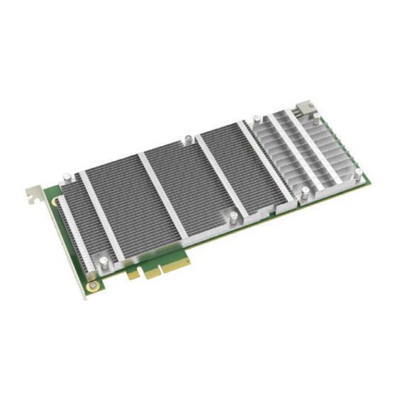
Introduction Hardware Overview PCIE-7207 card contains four Intel® Core™ i7 processor subsystems. Each subsystem communicates with the host server over its own Gigabit Ethernet link and supports 8GB of DDR3-1600 dual channel memory for a total of 32GB for the entire card. The PCIE-7207 card is a PCI Express compliant card of three-quarters length and full height with dimensions 239.83mm x 111.15mm.The PCIE-7207 card can be used as a Server Media Accelerator. -
Page 27: Software Overview
Introduction Software Overview 1.3.1 Host OS The recommended host OS is a standard 64-Bit CentOS 7.x Desktop Linux Distribution. The PCIE-7207 was tested on the host system running with CentOS 7.1. The Host OS needs to provide DHCP and TFTP services to enable the PCIE-7207 CPUs to obtain the IP address and PXE Boot their OS. -
Page 28: Standard Compliances
Introduction Standard Compliances The PCIE-7207 card meets the following standards. Table 1-1 Standard Compliances Standard Description EN55022: 2011 Class A CISPR 22: 2012 Radiated Emissions EN 300 386 V1.6.1: 2012 Class A EN 55022: 2011 FCC 15.109(b): 2015 Class A ANSI C63.4: 2003 FCC 15.109(g) (CISPR 22:1997): 2003 Class A ANSI C63.4: 2003 ICES-003 (Issue 5): 2012 Class A CAN/CSA-CISPR 22: 2008... - Page 29 Introduction Table 1-2 Ordering Information Part Number Description SL-DG7207-01-001-STD ViewCheck for PCIE-7207, single board license SharpStreamer™ PCIE-7207 Installation and Use (6806800T60F)
- Page 30 Introduction SharpStreamer™ PCIE-7207 Installation and Use (6806800T60F)
-
Page 31: Hardware Preparation And Installation
Chapter 2 Hardware Preparation and Installation This chapter will guide you through the hardware preparation and installation of the SharpStreamer™ PCIE-7207 card. It also lists the environmental, thermal, and power requirements for the PCIE-7207 card. Unpacking and Inspecting PCIE-7207 Card Damage of Circuits Electrostatic discharge and incorrect installation and removal of the card can damage circuits or shorten their life. -
Page 32: Environmental, Thermal, And Power Requirements
Hardware Preparation and Installation 3. Remove the desiccant bag shipped with the card and dispose of it according to your country’s legislation. The card is thoroughly inspected before shipment. If any damage has occurred during transportation please contact our Contact Center immediately. Environmental, Thermal, and Power Requirements This section contains the environmental, thermal, and power requirements of the PCIE-7207... -
Page 33: Power Requirements
Hardware Preparation and Installation Card Damage High humidity and condensation on the card surface causes short circuits. Do not operate the card outside the specified environmental limits. Make sure that the card is completely dry and there is no moisture on its surface before applying power. The following table provides the environmental and thermal requirements for the PCIE-7207 card. -
Page 34: Pcie-7207 Card Installation And Removal
Hardware Preparation and Installation Table 2-2 Power Requirements (continued) Mode PCIe slot power ATX 2x3 power Active 6W (+/- 10%) 60W (+/- 10%) Peak 120W (+/- 10%) Idle: All four Multi-Chip Packages (MCP) at Linux login prompt. Active: When the MCPs are in Transcoding state. Peak: When all the four MCPs are in turbo mode. -
Page 35: Pcie-7207 Card Installation
Hardware Preparation and Installation 2.3.1 PCIE-7207 Card Installation To install the PCIE-7207 card, perform the following steps: 1. Use antistatic pads and attach an ESD strap to your wrist. Attach the other end of the ESD strap to an electrical ground (For more details, refer to the section Unpacking and Inspecting PCIE-7207 Card on page 31). -
Page 36: Pcie-7207 Card Removal
Hardware Preparation and Installation MCP transcoding performance is directly related to the airflow and cooling ability of the server in which the card is installed. 2.3.2 PCIE-7207 Card Removal To remove the PCIE-7207 card, perform the following steps: 1. Make sure you are in an ESD-safe environment. 2. -
Page 37: Functional Description
Chapter 3 Functional Description Modern host server systems do not have advanced graphics processing capability and rely mostly on Xeon or other such server class processors for handling bulk network traffic and video transcoding functions. Though they can transcode video, they are not as efficient as a CPU/GPU combination System-on-Chip (SoC) would be. -
Page 38: Figure 3-1 Pcie-7207 Block Diagram
Functional Description The following figure depicts the functional block diagram of the SharpStreamer™ PCIE-7207 card. Figure 3-1 PCIE-7207 Block Diagram 20MB/s 20MB/s 20MB/s DDR3L DDR3L 20MB/s DDR3L Memory DDR3L Memory Keyboard DDR3L Keyboard Keyboard DDR3L DDR3L DDR3L DDR3L DDR3L Memory DDR3L Keyboard Memory... -
Page 39: Intel I350 Ethernet Controller
Functional Description Intel i350 Ethernet Controller The Intel i350 Quad Gigabit Ethernet Controller is the main interface between the Server PCIe bus and the Target Media Accelerator Processors. The Gigabit Ethernet Controller has an x4 PCIe Gen 2 bus (aggregate of 20Gbps throughput) connecting to the gold fingers of the PCIe edge card. -
Page 40: Power
Functional Description Power The PCIE-7207 card obtains power from two sources, one from the ATX style power connector (12V) and the other from the PCIe socket (3.3V). Currently, the PCIE-7207-4 card has the integrated Dell Remote Access Controller (iDRAC) FRU depopulated. Gigabit Ethernet Each MCP is connected to an Intel i218 Gigabit Ethernet PHY over the dedicated PCIe x1 channel 4. -
Page 41: Figure 3-2 Location Of Temperature Sensors
Functional Description The location of the temperatures sensors is shown in the Figure 3-2. Figure 3-2 Location of Temperature Sensors U128 temperature U120 temperature U121 temperature U130 temperature Primary Side U80 temperature U119 temperature U129 temperature temperature temperature Secondary Side The air temperature surrounding each sensor can be read via the I2C interface. -
Page 42: Microsd Card
Functional Description MicroSD Card There are four MicroSD cards mounted back-to-back along the top edge of the card near the faceplate. The MicroSD card is inserted from the top edge of the PCIE-7207 card. Each MicroSD goes to one of the respective MCPs. The MicroSD is designed for either a non-volatile storage space, and/or as a firmware recovery option. -
Page 43: Microsd As Firmware Recovery Option
Functional Description The following figure shows the location of the MicroSD cards and the corresponding MCPs on the board. Figure 3-3 MicroSD Card and MCP Location MicroSD MicroSD MCP4 MCP2 Primary Side MCP2 MCP3 MCP4 MCP1 MicroSD MicroSD MCP3 MCP1 Secondary Side 3.7.1 MicroSD as Firmware Recovery option... -
Page 44: Microsd As Non-Volatile Storage
Functional Description The pci7207 utility drives the i350 GPIO to the CPLD which drives the GPIO to the individual MCP-PCH to set the Insyde BIOS to recovery mode. When the MCP boots, the BIOS will sense the recovery GPIO and write the firmware BIOS from the MicroSD to the firmware chip. Then the MCP will reboot and the user can then connect to the MCP using VNC, SOL (amtterm) or Open Source Manageability Tool Kit to reconfigure the BIOS. -
Page 45: Reset Management
Functional Description Reset Management Each MCP reset is controlled by the CPLD. During power up the CPLD state machine drives the reset control to each MCP. During an induced reset from the server, the GPIO on the i350 controller triggers a reset to the CPLD GPIO input, which in turn sends the reset to the selected individual MCP processor complex through the CPLD GPIO. -
Page 46: Clock Management
Functional Description Clock Management Clocking for each MCP complex consists of two crystals. One 24Mhz crystal to drive all the main buses and a 32.768Khz crystal to drive the real time clock. The PCIe differential clock from the PCIe gold fingers connector goes to the i350 Quad Gigabit Ethernet controller. This clock source comes from the server in which the card is inserted into. -
Page 47: Controls, Indicators, And Connectors
Chapter 4 Controls, Indicators, and Connectors This chapter contains information about the Controls, Indicators, and Connectors associated with the PCIE-7207 card. Connectors The pinout descriptions of the key connectors on the PCIE-7207 card are provided in this section. 4.1.1 Edge Connector This section provides information about the PCIE-7207 card Edge Connector (Gold Finger) pinout. - Page 48 Controls, Indicators, and Connectors Table 4-1 PCIE-7207 Card Edge Connector Pinout (continued) Pin # Name Side B Description Name Side A Description WAKE# Signal for Link reactivation PERST# PCIe Edge PERST_L Main PCIe reset from the host system Mechanical Key RSVD Reserved Ground...
-
Page 49: Atx Power
Controls, Indicators, and Connectors Table 4-1 PCIE-7207 Card Edge Connector Pinout (continued) Pin # Name Side B Description Name Side A Description PETp3 PCIE3 EDGE TX P Ground PCIE3 EDGE TX N PETn3 Ground Transmitter Lane 3, Differential pair Ground PERp3 PCIE1 EDGE RX P PCIE1 EDGE RX N... -
Page 50: Figure 4-1 Led Arrangement View
Controls, Indicators, and Connectors The front panel LEDs are used to indicate the power status of the PCIE-7207 card. The LEDs derive their power from the PCIe gold finger 3.3V power. If the CPLD does not illuminate all the debug LEDs on powerup it means that CPLD does not have 3.3V power from the PCIe gold fingers. -
Page 51: Pcie-7207 Leds
Controls, Indicators, and Connectors The following table contains information about the LEDs on the PCIE-7207 card. Table 4-3 PCIE-7207 LEDs Label # Color Status Description Debug LEDs Green1 ON = MCP1 out of reset. OFF = MCP1 in reset. BLINKING = Server is holding MCP1 power off through i350 GPIO see “pci7207”... - Page 52 Controls, Indicators, and Connectors Table 4-3 PCIE-7207 LEDs (continued) Label # Color Status Description Amber1 Solid amber MCP1 CATERR# BLINKING amber MCP1 THERMTRIP# Amber2 Solid amber MCP2 CATERR# BLINKING amber MCP2 THERMTRIP# Amber3 Solid amber MCP3 CATERR# BLINKING amber MCP3 THERMTRIP# Amber 4 Solid amber MCP4 CATERR# BLINKING amber MCP4 THERMTRIP#...
-
Page 53: Controls
Controls, Indicators, and Connectors Controls A Reset button is available at the rear side of the PCIE-7207 card. By pressing the Reset button (labeled as S2), all the MCP processors on the card get reset. The following figure shows the Reset button location on the card. - Page 54 Controls, Indicators, and Connectors SharpStreamer™ PCIE-7207 Installation and Use (6806800T60F)
-
Page 55: Bios
Chapter 5 BIOS The Basic Input Output System (BIOS) acts as an interface between the operating system and the hardware of the card. Before loading the operating system, BIOS performs basic hardware tests and prepares the card for the initial boot-up procedure. Using BIOS Setup, you can perform the following tasks: Obtain system information ... -
Page 56: Accessing The Bios Setup Screen
BIOS Accessing the BIOS Setup Screen When the system is turned on or rebooted, the presence and functionality of the system components is tested by POST (Power-On Self Test). For more information on how to connect to the console PCIE-7207, refer the section Access a PCIE-7207 CPU via AMT on page The menus shown in the figures in this chapter are from a typical system. - Page 57 BIOS Select Save and Exit after making a selection in the setup menus. This procedure stores the selections displayed in the menus in CMOS. At the time of next boot up, BIOS configures the system according to the setup selection stored in CMOS. For more details, refer to the section Exit Menu on page 74.
-
Page 58: Menu Bar
BIOS 1. Press F2 to return to the BIOS setup. 2. Go to the Exit menu and select Load setup Defaults.The default BIOS values are loaded and the values will affect all setup items and also the previously altered reset options. The default values set become effective only after saving and exiting the BIOS setup. -
Page 59: Legend Bar
BIOS 5.2.2 Legend Bar The keys listed in the legend bar below on the BIOS Setup screen screen are used to make selections on screen or to move out of the current menu. The legend keys and their alternate options are explained in Table 5-3. -
Page 60: Field Help
BIOS 5.2.3 Field Help The help text of the selected field is displayed on the right side of the screen. By scrolling through each field, the related help text of the active selection is displayed. 5.2.4 General Help You can press F1 on the keyboard in any menu context to invoke the general help window. The general help window describes the legend keys and their alternates as shown in the following figure. -
Page 61: Main Menu
BIOS 5.3.1 Main Menu To view the Main menu, select the Main tab from the menu bar. By default, the Main tab is selected on the BIOS Setup screen. To modify menu screen items, scroll down the Main screen. The following screen appears. Figure 5-3 Main menu SharpStreamer™... -
Page 62: Advanced Menu
BIOS The following table provides the list of features that can be configured in Main menu and their default values. Table 5-4 Main menu Selection Options/Format Description Language English/French/Chinese/Japanese Set the setup language System Time HH:MM:SS Set the system time System Date MM/DD/YYYY Set the system date... -
Page 63: Boot Configuration
BIOS The following table provides a brief description about the list of configurations that can be performed in the Advanced menu. Table 5-5 Advanced menu Feature Description Boot Configuration Select the boot configuration Console Redirection Change console redirection parameter Serial IO Configuration Change device options to enable the debug UART 5.3.2.1 Boot Configuration... -
Page 64: Table 5-6 Boot Configuration
BIOS The following table provides information about options in the Boot Configuration submenu and their default values. The values shown in the tables enclosed within brackets [...] indicate the default settings. Table 5-6 Boot Configuration Feature Options Description Numlock [On] Enables or disables Numlock SharpStreamer™... -
Page 65: Console Redirection Setup
BIOS 5.3.2.2 Console Redirection Setup The following figure shows the Console Redirection Setup submenu screen. The settings are applied to all ports, if selected. Individual submenus are available, if there is a need for separate port configuration. Figure 5-6 Console Redirection Setup The following table provides information about the feature options in the Console Redirection Setup submenu and their defaults values. - Page 66 BIOS Table 5-7 Console Redirection Setup (continued) Feature Option Description Baud Rate [115200] Selects the baud rate 57600 38400 19200 9600 4800 2400 1200 Data Bits 7 Bits Selects the data bits [8 Bits] Parity [none] Selects the parity Even Stop Bits [1 Bit] Selects the stop bits...
-
Page 67: Serial Io Configuration
BIOS Table 5-7 Console Redirection Setup (continued) Feature Option Description AutoRefresh Disabled Selects if the terminal will be refreshed after a console is detected [Enabled] FailSafeBaudRate [Disabled] Selects if the baud rate automatically changes to one of the terminals it can be Enabled detected. -
Page 68: Security Menu
BIOS The following table provides information about Serial IO Configuration submenu options and their default settings. Table 5-8 Serial IO Configuration Feature Option Description DMA Controller [Disabled] Enable or disable the PCI DMA controller Enabled UART0 Controller [Disabled] Enable or disable the PCI UART0 controller Enabled 5.3.3 Security Menu... -
Page 69: Power Menu
BIOS The following table provides other options in the Security menu and their defaults. The values shown in the tables enclosed within brackets [...] indicate the default settings. Table 5-9 Security menu Feature Option Description Set Supervisor Password Sets the password 5.3.4 Power Menu To view the Power menu, select the Power tab from the menu bar. -
Page 70: Advanced Cpu Control
BIOS The following table provides other options in the Power menu and their defaults. Table 5-10 Power menu Feature Options Description Advanced CPU Control Select CPU features 5.3.4.1 Advanced CPU Control The following figure shows the Advanced CPU Control submenu. Figure 5-10 Advanced CPU Control The following table provides options in the Advanced CPU Control submenu and their... - Page 71 BIOS Table 5-11 Advanced CPU Control (continued) Feature Options Description Excute Disable Bit Disabled Enables or disables the CPU feature to classify areas of [Enabled] memory where code can or cannot be executed Intel (VMX) Virtualization [Enabled] Enables or disables the CPU Technology virtualization support Disabled...
-
Page 72: Boot Menu
BIOS 5.3.5 Boot Menu To view the Boot menu, select Boot tab on the menu bar. The Boot menu screen is displayed as shown below. Figure 5-11 Boot menu The following table provides options in the Boot menu and their default settings. Table 5-12 Boot menu Feature Option... - Page 73 BIOS Table 5-12 Boot menu (continued) Feature Option Description Network Stack Disabled Enables or disables UEFI and Legacy network support [Enabled] PXE Boot capability Disabled Enables or disables the alternate PXE boot modes UEFI:IPv4 UEFI:IPv6 UEFI:IPv4/IPv6 [Legacy] Add Boot Options First Selects the position of an added boot device Last...
-
Page 74: Exit Menu
BIOS 5.3.6 Exit Menu To view the Exit menu, select Exit tab from the menu bar. Use the legend keys to make a selection or exit to the main menu. The Exit menu screen looks similar to the figure below. Figure 5-12 Exit menu The following table provides Exit menu features and their description. -
Page 75: Updating The Bios
BIOS Updating the BIOS For information on updating the BIOS on the PCIE-7207 card, refer to the section BIOS Update on page SharpStreamer™ PCIE-7207 Installation and Use (6806800T60F) - Page 76 BIOS SharpStreamer™ PCIE-7207 Installation and Use (6806800T60F)
-
Page 77: Software Installation
Chapter 6 Software Installation In order to control, configure, and interact with the PCIE-7207 card installed in the host system you need to install the core OS and required applications on top of the host system. This chapter provides information on how to prepare a host system and also the prerequisites required for installing PCIE-7207 OS and pci7207 utility. -
Page 78: Firewall Configuration
Software Installation tftp-server syslinux To install the above listed packages on the host system: 1. Log in to the host system as root 2. Run the following commands. yum install epel-release yum install dhcp yum install tftp-server yum install syslinux 6.1.1.1 Firewall Configuration The CentOS 7.1 installation has the Firewall service enabled by default. -
Page 79: Pci7207 Utility Installation
Software Installation To enable TFTP server: 1. Log in to the host as root. 2. Run the following commands. cd / ln –s /var/lib/tftpboot /tftpboot 3. Modify the file /etc/xinetd.d/tftp with the editor. 4. Change disabled = yes to disabled = no, save the file and exit. 5. -
Page 80: Dhcp Configuration
Software Installation 6.1.1.5 DHCP Configuration The PCIE-7207 CPUs will obtain their IP addresses from the host system via DHCP. For this process to work, it is necessary to create a DHCP configuration file and to initialize the host Ethernet interfaces associated with the PCIE-7207 cards in the host system. 1. -
Page 81: Pcie-7207 Os Installation
Software Installation PCIE-7207 OS Installation To install the PCIE-7207 OS: 1. Copy the PCIE-7207 OS image to the host system. Obtain the latest version of the PCIE-7207 OS image using the SWORDS download server available from the Artesyn Customer Resource Center Website (http://crcportal.artesyn.com). -
Page 82: Network Interfaces
Software Installation 6.3.1 Network Interfaces The pci7207 utility used to initialize the network interfaces creates an internal network with separate subnets for each PCIE-7207 Ethernet interface. The pci7207 utility finds all the PCIE- 7207 cards in the system and assigns them a CARD ID to each one based on their PCI bus. It then uses the CARD ID and CPU number to create the separate subnets as, 172.20.<card id><cpu>.1 for the PCIE-7207 Host Ethernet interface, and 172.20.<card id><cpu>.100 for the corresponding PCIE-7207 CPU Ethernet interface. -
Page 83: Log On To A Pcie-7207 Cpu
Software Installation 6.3.2 Log on to a PCIE-7207 CPU To log on to a PCIE-7207 CPU, it is necessary to log in to the host system first, then to the PCIE- 7207 CPU. 1. Log in to the host as root 2. -
Page 84: Connect To A Pcie-7207 Cpu Using Amtterm
Software Installation yum install amtterm-1.3-1.el6.x86_64.rpm Get the updated amtterm source code, compile it, and install it. wget http://www.senseless.info/downloads/amtterm-patched.tar.gz tar zxf amtterm-patched.tar.gz cd amtterm ./build.sh cd amtterm-1.3 cp amtterm amttool /usr/local/bin cd /root rm –rf tmp The best way to install amtterm in a CentOS 7.1 host is to get the CentOS 6.5 amtterm and then install it using yum to get all the dependencies installed as well. -
Page 85: Software Upgrade
Software Installation connected now, use ^] to escape CentOS Linux 7 (Core) Kernel 3.10.0-229.1.2.36242.MSSr5.el7.centos.x86_64 on an x86_64 pcie7207 login: Login to the CPU using “root” as the user and “root” as the password pcie7207 login: root Password: Last login: Thu Jan 30 09:29:08 on ttyS0 [root@pcie7207 ~]# Only one AMT connection is allowed per MCP. -
Page 86: Software Removal
Software Installation Software Removal To remove the PCIE-7207 OS and the pci7207 utility from a host system: 1. Log in to the host system as root. 2. Remove the PCIE-7207 OS image. cd /tftpboot rm –rf pcie7207 rm -f pxelinux.cfg/default 3. -
Page 87: Utilities And Applications
Chapter 7 Utilities and Applications The PCIE-7207card comes with the tool pci7207 utility. This chapter provides more information about pci7207 utility and its usage. In addition to that the PCIE-7207 OS related information such as sensor information, BIOS update and AMT provisioning is explained in this chapter. -
Page 88: Pci7207 Usage
Utilities and Applications 7.1.1 pci7207 Usage The following section contains the list of commands in pci7207 utility. Display utility help # pci7207 -h Usage: pci7207 options Options: Display version Display help Backwards compatibility -s ID PCIE-7207 card id 1-24 -n CPU CPU 1 - 4 -c CMD... - Page 89 Utilities and Applications # pci7207 -b -cl CARD SIZE CPU MAC INTF 01:00.0 0xf7800000 0x100000 ec:9e:cd:15:d7:8c enp1s0f0 01:00.1 0xf7700000 0x100000 ec:9e:cd:15:d7:8d enp1s0f1 01:00.2 0xf7600000 0x100000 ec:9e:cd:15:d7:8e enp1s0f2 01:00.3 0xf7500000 0x100000 ec:9e:cd:15:d7:8f enp1s0f3 02:00.0 0xf7300000 0x100000 ec:9e:cd:15:e9:c9 enp2s0f0 02:00.1 0xf7200000 0x100000 ec:9e:cd:15:e9:ca enp2s0f1 02:00.2...
- Page 90 Utilities and Applications host enp1s0f0_cpu1 { hardware ethernet ec:9e:cd:14:d4:5d; fixed-address 172.20.11.100; } subnet 172.20.12.0 netmask 255.255.255.0 { option broadcast-address 172.20.12.255; next-server 172.20.12.1; host enp1s0f1_cpu2 { hardware ethernet ec:9e:cd:14:d4:5e; fixed-address 172.20.12.100; } subnet 172.20.13.0 netmask 255.255.255.0 { option broadcast-address 172.20.13.255; next-server 172.20.13.1; host enp1s0f2_cpu3 { hardware ethernet ec:9e:cd:14:d4:5f;...
- Page 91 Utilities and Applications option broadcast-address 172.20.23.255; next-server 172.20.23.1; host enp2s0f2_cpu3 { hardware ethernet ec:9e:cd:15:e9:cb; fixed-address 172.20.23.100; } subnet 172.20.24.0 netmask 255.255.255.0 { option broadcast-address 172.20.24.255; next-server 172.20.24.1; host enp2s0f3_cpu4 { hardware ethernet ec:9e:cd:15:e9:cc; fixed-address 172.20.24.100; }} Generate a DHCP configuration with routers and ntp-servers options. You can redirect the ...
- Page 92 Utilities and Applications subnet 172.20.13.0 netmask 255.255.255.0 { option broadcast-address 172.20.13.255; option routers 172.20.13.1; option ntp-servers 172.20.13.1; next-server 172.20.13.1; host enp1s0f2_cpu3 { hardware ethernet ec:9e:cd:14:d4:5f; fixed- address 172.20.13.100; } subnet 172.20.14.0 netmask 255.255.255.0 { option broadcast-address 172.20.14.255; option routers 172.20.14.1; option ntp-servers 172.20.14.1;...
- Page 93 Utilities and Applications host enp2s0f2_cpu3 { hardware ethernet ec:9e:cd:15:e9:cb; fixed- address 172.20.23.100; } subnet 172.20.24.0 netmask 255.255.255.0 { option broadcast-address 172.20.24.255; option routers 172.20.24.1; option ntp-servers 172.20.24.1; next-server 172.20.24.1; host enp2s0f3_cpu4 { hardware ethernet ec:9e:cd:15:e9:cc; fixed- address 172.20.24.100; } Generate ifconfig statements to initialize the local interfaces. ...
- Page 94 Utilities and Applications – Power Cycle all CPUs in all PCIE-7207s in the system # pci7207 –cp Execute BIOS Crisis Recovery for a PCIE-7207 CPU. Executing a BIOS Crisis Recovery for a PCIE-7207 CPU requires a MicroSD card to be inserted in the MicroSD slot for the PCIE-7207 CPU.
-
Page 95: Pcie-7207 Os
Utilities and Applications PCIE-7207 OS 7.2.1 Sensor Information The PCIE-7207 OS has a utility to display sensor information locally on each CPU. 1. Log in to the host system as root 2. Log in to a PCIE-7207 CPU as root 3. -
Page 96: Amt Provisioning
Utilities and Applications 3. Copy the BIOS image from the host system to the PCIE-7207 CPU to update and place it in /root and execute the BIOS update utility. In the example below CARD 1 CPU 1 are used. scp pcie7207_<BIOS release>_signed.fd 172.20.11.100:/root amtterm –pP@ssw0rd 172.20.11.100 cd /opt/InsydeBios ./H2OFFTx64.sh /root/pcie7207_<BIOS release>_signed.fd –BIOS... -
Page 97: Setting Linux Date And Time Manually
Utilities and Applications 7.2.4 Setting Linux date and time manually This section provides a brief description about the commands that are used for manually setting Linux date and time. Assuming that you have an NSF mounted rootfs or booting from SSD/HD/uSD. It applies to both SharpServer and SharpStreamer cards. - Page 98 Utilities and Applications Thu Mar 10 13:35:37 PST 2016 If you do not update the required time zone in /etc/profile, the time zone will again set to MST when you reboot the system. SharpStreamer™ PCIE-7207 Installation and Use (6806800T60F)
-
Page 99: Ssf Installation
SSF release contains two sets of RPMs, one set for the PCIe Server host and the other set for the MCPs on the PCIE-7207 card. For more information about SSF on PCIE-7207, refer to SSF on SharpStreamer PCIE-7207 User Guide. SSF RPMs and Dependent Packages SSF software is delivered as a complete package, which includes SSF packages, dependent packages and an installation script. - Page 100 SSF Installation Table 8-1 List of SSF and Dependent RPMs for Host (continued) Description Provides binary and configuration files of the Blade ssf_bcsim_rel-<Version>- Common System Information Model (BCSIM). This el7.x86_64.rpm also includes the Linux service configuration file. The BCISM is used to configure and maintain the OS services, Interfaces, OS information, and so on.
-
Page 101: Install Ssf On Host
SSF Installation Table 8-2 List of SSF and Dependent RPMs for MCP Package Description SSF MCP Agent Client Provides SSF agent for configuration and ssf_mcpagtclnt_rel-<Version>- management for MCP on PCIE-7207 tested with PCIe- el7.x86_64.rpm 7207 BBS DA-08. Dependent RPMs To help with the construction and handling of libnet-1.1.6-7.el7.x86_64.rpm network packets. - Page 102 SSF Installation 6. Execute the following script to install SSF. $./SsfPCIE-7207SetupOnEL7.sh ############################################################### # The complete installation procedure is divided into the following categories: # 1. SSF-PCIE-7207 Installation # 2. SSF-PCIE-7207 Uninstallation # 3. Upgrade SSF-PCIE-7207 # Please choose the option "1" to Install SSF-PCIE-7207, Zend and dependent rpms # "2"...
- Page 103 SSF Installation Installation of dependent packages for zend takes time. Please wait... Installation of dependent packages for zend done. Installation of Zend Framework takes time. Please wait... Installation of Zend Framework...Done. Installation of Dependent packages takes time. Please wait... Installation of Dependent packages...Done. Installation of ssf pcie-7207 packages takes time.
-
Page 104: Installation Script
SSF Installation 8.2.1.1 Installation Script The installation script ./SsfPCIE-7207SetupOnEL7.sh performs the following things: 1. Installs dependent packages. For more information about dependent packages, refer to Table "List of SSF and Dependent RPMs for Host" on page 2. Changes firewall configuration to allow SSF communication messages. For more information about firewall configuration settings, refer to the section Firewall Configuration on page... -
Page 105: Uninstalling Ssf From Host System
SSF Installation 3. Restart SSF services. firewall-cmd --reload 8.2.2 Uninstalling SSF from Host System To uninstall SSF on host system: 1. Log in to the host system as root 2. Execute the following script to uninstall the SSF from host. ./SsfPCIE-7207SetupOnEL7.sh ############################################################### #######################################... -
Page 106: Install Ssf Agent On Mcp
SSF Installation Please enter your choice: 3. Enter 2 to select SSF-PCIE-7207 Uninstallation. Uninstallation of ssf pcie packages takes time. Please wait... ssfbcsimd is not running... ssfbcsimd is already stopped. Uninstallation of ssf pcie-7207 packages...Done. Uninstallation of Dependent packages takes time. Please wait... Uninstallation of Dependent rpms done. - Page 107 SSF Installation If these packages are not available in standard BBS release, install them on PCIE-7207 OS along with the SSF package for MCP. These packages are provided under the directory ssf-mcp-rpms in the standard SSF package. The procedure on how to include an RPM with PCIE-7207 OS is described in the section Update PCIE-7207 OS with SSF MCP Agent Client and ViewCheck on page 113.
- Page 108 SSF Installation SharpStreamer™ PCIE-7207 Installation and Use (6806800T60F)
-
Page 109: Viewcheck Installation
Chapter 9 ViewCheck Installation SSF provides access to ViewCheck™, a licensed software which provides in-service and out-of- service diagnostics suite to test and monitor the hardware. This is a licensed application and can be downloaded using the SWORDS download server available from the Artesyn Customer Resource Center Website after getting valid licenses. - Page 110 ViewCheck Installation rpm -ivh diagnostics-lib- <RELEASE>_<BUILD>.<DIST>.<OS>.pcie7207.rpm The command changes the firewall settings automatically only when the firewall configuration is in enable mode at the time of installation. If the Firewall configuration is in enable mode at the time of installation, the above command automatically enables specific ports 21000 and 25678 (for internal communication of ViewCheck) and proceeds with the ViewCheck installation.
-
Page 111: Install Viewcheck On Mcp
ViewCheck Installation rpm -e diagnostics-lib-<RELEASE>_<BUILD>.<DIST>.<OS>.pcie7207 The installation and uninstallation of ViewCheck Interface library depends on ssf_diag_rel-centos-<Version>.x86_64.rpm Install ViewCheck on MCP The ViewCheck RPM for MCP is the ViewCheck core daemon provided in the following format. diagnostics-<RELEASE>_<BUILD>.<DIST>.<OS>.pcie7207.rpm For more information on how to include a ViewCheck RPM to PCIE-7207 OS, refer to the section Update PCIE-7207 OS with SSF MCP Agent Client and ViewCheck on page 113. - Page 112 ViewCheck Installation SharpStreamer™ PCIE-7207 Installation and Use (6806800T60F)
-
Page 113: Ssf And Viewcheck
Appendix A SSF and ViewCheck This section helps you to understand how to add SSF MCP Agent Client and ViewCheck packages to an existing PCIE-7207 OS (initramfs). A script updatePCIe-7207-OS.sh is provided as a reference implementation on how to add SSF MCP Agent Client and ViewCheck packages to a PCIE-7207 OS image. This script is part of standard SSF release. - Page 114 SSF and ViewCheck -r <rpm-location> : path of the directory containing diag released RPM(s) -t <temporary-location> : path of the temporary directory which will be used for extracting and and modifying the ramdisk image :help message For example, sh diagInstall.sh -i /tftpboot/pcie7207/initramfs- 3.10.0-229.1.2.36242.MSSr5.cpio.gz -r /home/rpms/ -t /tmp The modified PCIE-7207 OS image will be generated at the same location as the original PCIE-7207 OS image.
-
Page 115: Related Documentation
Table B-1 Artesyn Embedded Technologies - Embedded Computing Publications Document Title Publication Number SharpStreamer PCIE-7207 Quick Start Guide 6806800T58 SharpStreamer PCIE-7207 Safety Notes Summary 6806800T59 ViewCheck on SharpStreamer-PCIE-7207 User Guide 6806800T61 SSF on SharpStreamer PCIE-7207 User Guide 6806800T63 SharpStreamer™ PCIE-7207 Installation and Use (6806800T60F) - Page 116 Related Documentation SharpStreamer™ PCIE-7207 Installation and Use (6806800T60F)
- Page 118 Artesyn Embedded Technologies, Artesyn and the Artesyn Embedded Technologies logo are trademarks and service marks of Artesyn Embedded Technologies, Inc. All other product or service names are the property of their respective owners. © 2016 Artesyn Embedded Technologies, Inc.
Need help?
Do you have a question about the SharpStreamer PCIE-7207 and is the answer not in the manual?
Questions and answers