Table of Contents
Advertisement
Quick Links
TOHO ELECTRONICS INC.
Program Controller TTM-P4W Series
Instruction Manual
Thank you for purchasing our Program Controller TTM-P4W Series. Please read this
Instruction Manual carefully to use the product correctly. TTM-P4W Series is a
simplified program controller which enables program operation of up to "Patterns x
Steps = 64".
1.
Cautions on Use ................................................................... 1
2.
Name and Size of Each Part ................................................ 2
3.
Wiring .................................................................................. 4
4.
Terms and Functional Description ...................................... 5
5.
Before Program Operation .................................................. 8
6.
Operation Flow and Parameter Description ........................ 9
7.
Setting and Display Ranges ............................................... 20
8.
Specifications and Rating .................................................. 21
9.
Maintenance and Inspection .............................................. 23
Contents
Advertisement
Table of Contents

Related Manuals for Toho Electronics TTM-P4W Series

Summary of Contents for Toho Electronics TTM-P4W Series
-
Page 1: Table Of Contents
Program Controller TTM-P4W Series Instruction Manual Thank you for purchasing our Program Controller TTM-P4W Series. Please read this Instruction Manual carefully to use the product correctly. TTM-P4W Series is a simplified program controller which enables program operation of up to "Patterns x Steps = 64". -
Page 2: Cautions On Use
1. Cautions on Use For safety purpose, following symbols are used in this manual. The case that a user may receive fatal damage, electric shock, or severe burn Warning injury when the product is incorrectly used. The case that a user may receive minor damage or the equipment may get Caution damage. -
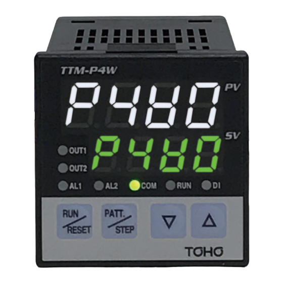
Page 3: Name And Size Of Each Part
2. Name and Size of Each Part 2.1 Name of each part LED Lamp RUN: Lights during operation mode OUT1: Lights when control output 1 is ON (closed) and turns off when control output 1 is OFF (open). OUT2: Lights when control output 2 is ON (closed) and turns off when control output 2 is OFF (open). - Page 4 2.2 External dimensions and panel cut size...
-
Page 5: Wiring
3. Wiring 3.1 TTM-P4W series Communication (RS-485) 3.2 Caution on wiring Before wiring, be sure to turn off the power supply. Otherwise, you may get an Warning electric shock. This equipment does not execute control operation for about 4 seconds after the Caution power is turned on. -
Page 6: Terms And Functional Description
4. Terms and Functional Description 4.1 Set the Number of Patterns - The maximum number of steps are determined depending on the number of patterns. - The relationship between the number of patterns and the maximum number of steps is as shown in the table below. Number of Patterns Maximum number of Steps 4.2 Event Output 1 / Event Output 2... - Page 7 4.3 Wait operation If the measured value (PV) has not reached the Wait Zone after the step time has elapsed, the next step will not start. However, after the wait time has elapsed, the next step begins. At the wait operation, the indication at SV blinks.
- Page 8 SV start...Program operation starts from the SV start temperature setting " ". Start operation from this point. step 1 step2 step3 step4 4.5 Time Signal Output It is a function to output at any time at the start of operation or at the transition to the next step. ON Time OFF Time Time Signal...
-
Page 9: Before Program Operation
5. Before Program Operation You can select the input type. Thermocouple(K, J, R, T, N, S, B) and RTD(Pt100) are provided for this product. In this Instruction Manual, the following symbol is used in order to use this equipment safely. Caution Before using this equipment, be sure to set the input type. -
Page 10: Operation Flow And Parameter Description
6. Operation Flow and Parameter Description 6.1 State transitions between modes Operation keys will be used to switch between modes. △ + PATT./STEP for 5 seconds (*1) Common parameter Reset mode Programming mode setting mode RUN/RESET RUN/RESET for 5 sec. RUN/RESET RUN/RESET RUN/RESET... - Page 11 6.2 Detailed description of modes ① Reset mode - This mode will stop control. (The system becomes this mode when the power is turned on.) ② Operation mode - This mode will conduct programmed run control. (The RUN lamp lights.) - The SV display will blink while a wait operation is in process in the wait zone or wait time.
- Page 12 ⑤ Programming mode - This mode will set the program for each pattern. - Setting the time to 0 minutes will invalidate that particular step. From reset mode From operation mode Press PATT./STEP. Hold PATT./STEP down Pattern number setting mode for 3 seconds.
- Page 13 ⑥ Common parameter setting mode - This mode will set the parameter common to each pattern and step. From reset mode Hold the △ key and the PATT./STEP key down for 5 seconds simultaneously. Set the PV correction zero point. ...
- Page 14 Set "Event Output 1 sensitivity setting". It is hidden when Time signal is selected. Press the PATT./STEP key. Set "Event Output 2 sensitivity setting". It is hidden when Run Signal Output is selected. Press the PATT./STEP key. Set "Time signal ON time setting".
- Page 15 Set "Control type setting". Press the PATT./STEP key. Set "OUT1 function setting". Press the PATT./STEP key. Set "OUT2 function setting". Press the PATT./STEP key. Set "Main control proportional band low temperature setting". It is hidden when the main control is selected to "ON / OFF control". ...
- Page 16 Press the PATT./STEP key. Start the automatic tuning of PID No. 1 (low temperature control zone). → Temperature setting for automatic tuning It is hidden when the main control is selected to "ON / OFF control". [RUN/RESET] key Press the PATT./STEP key.
- Page 17 About the setting method of the type setting of "Time signal / Event Output 1" and the type setting of "Run Signal Output / Event Output 2". Action types (to be set by using the ▽ key) Additional functions (to be set by using the △ key) No additional functions <"Time signal / Event Output 1"...
- Page 18 6.3 Parameter description Program setting mode parameters Character Description Initial value Setting range □ Set a step □ temperature Setting range (K: 0 to 1300 C/J: 0 to 800C/R: 0 to 1700C/ T: 0 to 1300 C/N: 0 to 800C/S: 0 to 1700C/ B: 0 to 1800 C /S: 0 to 1700C/Pt100Ω: 0.0 to 500.0C) □...
- Page 19 Character Description Initial value Setting range 0: PV(measured value) output Transmission output 1: SV(set value) output function 2: MV1(main control operation amount) output 3: MV2(sub-control operation amount) output 4: Control SV output Transmission output 1200 measuring range lower limit to measuring range upper limit *1 scaling upper limit Transmission output measuring range lower limit to measuring range upper limit *1...
- Page 20 Control setting mode parameters Character Description Initial value Setting range Main control Sub-control ON/OFF Control type ON/OFF ON/OFF ON/OFF 0:Main output 1:Sub-output OUT1 function 2:Transmission output(for analog output) 0:Main output 1:Sub-output OUT2 function 2:Run Signal Output / Event Output 0.1 to 200.0 % Main control proportional 3.0% band low temperature...
- Page 21 Character Description Initial value Setting range <Thermocouple > 1C 0 to 199 C Main control sensitivity <resistance temperature detector> 0.0 to 199.9 C <Thermocouple > 0C 0 to 199 C Main control off-point <Resistance temperature detector> position 0.0 to 199.9 C 0 to 99 minutes Main control protection off 0minutes...
-
Page 22: Setting And Display Ranges
7. Setting and Display Ranges Measuring Range and Designated Resolution Measuring/Display Designated Input Type Setting Range Range Resolution -210 to 1382 -200 to 1372 1℃ -210 to -200 to 1℃ -10 to 1710 0 to 1700 1℃ Thermocouple -210 to -200 to 1℃... -
Page 23: Specifications And Rating
8. Specifications and Rating 8.1 General specifications Storage cell Each setting value is stored in EEPROM. Power supply voltage 100 to 240 VAC ±10%, 50/60Hz (free power supply) Power consumption 10 VA or less Measuring terminal – case: 500 VDC, 20 M Insulation resistance Power supply terminal –... - Page 24 8.2 Rating and performance Input Thermocouple K, J, R, T, N, S, B (JIS C1602-2015) When a wire is disconnected: Indicated as " " Display Accuracy ±(0.3%+1 digit) of the input value or ±2℃, whichever is higher (ambient temperature 23±10℃) Provided that -99 to 0℃...
-
Page 25: Maintenance And Inspection
9. Maintenance and Inspection 9.1 Error indication: : Memory error (Abnormality of EEPROM) : A/D conversion error (Abnormality of A/D conversion) : Automatic tuning error TOHO ELECTRONICS INC. Head Office: 2-4-3 Nishihashimoto midori-ku sagamiharashi Kanagawa 252-0131 Japan Tel: +81-42-700-2100 Fax: +81-42-700-2112 Web.
Need help?
Do you have a question about the TTM-P4W Series and is the answer not in the manual?
Questions and answers