Advertisement
Quick Links
IN-V300-08
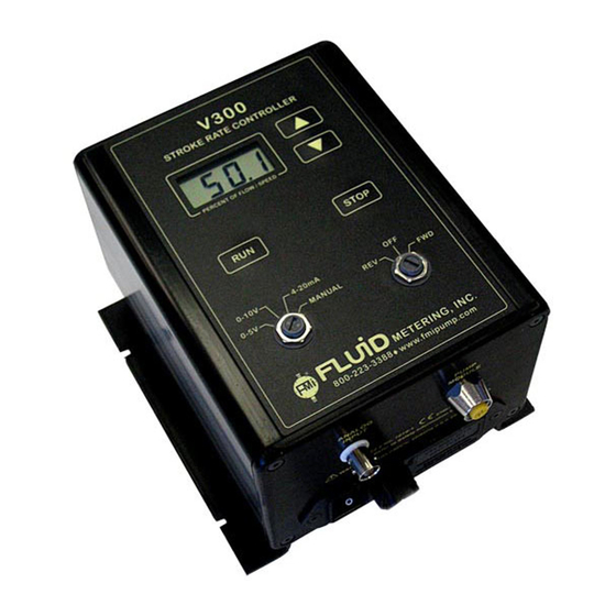
V300 SET UP INSTRUCTIONS
!
Before using any Fluid Metering, Inc. product read the following safety instructions
as well as specific product specifications and operating instructions.
!
Warning! Fire, electrical shock or explosion may occur if used near combustibles
explosive atmosphere, corrosive air, wet environment or submerged in fluid.
Turn off the electrical power before checking pump for any problems.
Connect motor, speed controllers, or any other electrical devices
based on Fluid Metering Inc. specifications. Any unauthorized work
performed on the product by the purchaser or by third parties can
impair product functionality and thereby relieves Fluid Metering, Inc.
of all warranty claims or liability for any misuse that will cause
damage to product and/or injury to the individual.
Power cables and leads should not be bent, pulled or inserted by
excessive force. Otherwise there is a threat of electrical shock or fire.
Replace any inline fuses only with fuse rating as specified by
Fluid Metering, Inc.
When pump/drive is under operation, never point discharge tubing
into face or touch any rotating components of pump. In a power
down thermal overload cut-in condition, unplug or turn off power
to pump. Always allow a cool down period before restarting:
otherwise, injury or damage may occur.
For 30 seconds after power is removed from pump/drive: do not
touch any output terminals. Electrical shock may occur because of
residual voltage.
FOR ADDITIONAL REFERENCES SEE H431 AND Q431
SAFETY INSTRUCTIONS
Figure 1
!
Caution! Fire, electrical shock, injury and damage may
occur if not used in accordance with Fluid Metering, Inc.
specifications and operation instructions.
Do not put wet fingers into power outlet of unit.
Do not operate with wet hands.
Do not operate drive assemblies that require a hard mount
(to be bolted down) unless they are mounted per Fluid Metering.
specifications, if not injury may occur and/or damage to unit.
Do not touch any rotating pump or motor components: injury
may occur.
Do not run pump dry, unless designed for that service.
Running dry is harmful to the pump, and will cause excessive
heating due to internal friction.
Check pump rotation and inlet/outlet pump port orientation
before connecting power to pump. If not injury may occur.
When pulling out cords from outlets do not pull cord, grasp
plug to prevent plug damage or electrical shock.
Fluid Metering, Inc. Drive Motors become HOT and can
cause a burn
. DO NOT TOUCH!
Figure 2
1
Advertisement

Subscribe to Our Youtube Channel
Summary of Contents for FMI V300
- Page 1 IN-V300-08 V300 SET UP INSTRUCTIONS FOR ADDITIONAL REFERENCES SEE H431 AND Q431 SAFETY INSTRUCTIONS Before using any Fluid Metering, Inc. product read the following safety instructions as well as specific product specifications and operating instructions. Warning! Fire, electrical shock or explosion may occur if used near combustibles explosive atmosphere, corrosive air, wet environment or submerged in fluid.
- Page 2 V300 Controller Before moving on to configuring the control module, and a variable speed "V" Series Pump. The V300 and make sure that these rubber grommets are in place. pump are connected via a single cable (standard There are no further installation steps for table top use.
- Page 3 Stroke Rate Maximum is displayed on the LCD for easy monitoring. To run the V300 system in 0-10 V Mode, simply turn the Mode Switch to "0-10 V" using a screwdriver. (See a) 0-5 Volt Mode: Use this mode to remotely control Figure 1) the stroke rate with a voltage source of 0 to 5 VDC.
- Page 4 CAUTION CHECK LIST Make sure the Power Switch is turned off prior to con- To run the V300 system in 4-20 mA mode, simply turn necting the approved power cable to the AC power out- the Mode Switch to "4-20 mA" using a screwdriver.
- Page 5 The V300 requires two (2) 5x20mm 1 A - This design provides maximum torque to handle tem- 250 VAC Time Lag fuses. If the V300 blows these new...
- Page 7 5.75 146.1 V300 V300 MOUNTING TEMPLATE OUTLINE Figure 4...
Need help?
Do you have a question about the V300 and is the answer not in the manual?
Questions and answers