Table of Contents
Advertisement
Quick Links
Advertisement
Table of Contents

Summary of Contents for Funktel TETRA FT4
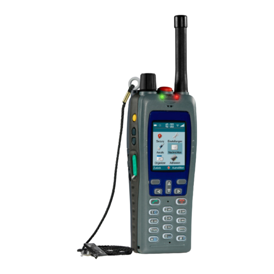
- Page 1 TETRA radio Funktel FT 4/FT 5 S (UHF/VHF) Operating manual ...
- Page 2 No part of this operating manual may be reproduced or copied in any form (printing, photocopying or other processes) without the written approval of Funktel GmbH. We reserve the right to modify this Operating Manual at any time and without prior announcement.
-
Page 3: Table Of Contents
Contents Contents Instructions for use ....................7 Before commissioning ....................7 Equipment and type designation ................. 7 Attention: Explosion-proof version ................7 FT4/FT5 device models ....................8 Technical terms and abbreviations ................9 Symbols and special fonts ..................12 Design and function .................... - Page 4 Contents Charging the battery ....................44 • Charging the FT4 battery with a Desktop Charger II FT4/Desktop Station FT4 ... 44 • Charging the FT5 battery with a Desktop Charger FT5/Desktop Station FT5 and 44 • Battery Charger FT5 ..................... 44 •...
- Page 5 Contents Key lock ........................101 • Locking the keys ....................101 • Unlocking the keys ..................... 102 Open listening mode ON/OFF during a call ............103 Muting the microphone during a call ............... 104 Brief instructions for selected functions ..............104 “Device functions by speed dial”...
- Page 6 Contents Service and cleaning ..................... 141 Care information ...................... 141 Care instructions for the batteries ................142 Technical data of the FT4 ..................143 Mechanical and electrical properties ............... 143 TETRA-specific features ..................143 Operating conditions ....................144 Energy supply data ....................144 Side connector ......................
-
Page 7: Instructions For Use
The type designation on the type plate provides detailed information about the fea- tures of your radio set. Attention: Explosion-proof version The funktel FT4 radio set is also available in explosion-proof versions. To ensure safe handling, it is imperative that you read and follow Ex Safety Note... -
Page 8: Ft4/Ft5 Device Models
= 146 ... 175 MHz (FT5 only) Output classification 1 = 1 W 2 = 2 W 3 = 3 W Separation <underscore> FT4 <blank> = Standard FT5 <blank> = Standard = SECURITY Separation <blank space> Device type = FT4 or FT5 funktel TETRA™... -
Page 9: Technical Terms And Abbreviations
Instructions for use Technical terms and abbreviations Technical terms and abbreviations Overview Term Description Air Interface Encryption: air interface encryption BetrSichV German Ordinance on Industrial Safety and Health Ordinance concerning safety and health protection when furnishing work equipment and its use for work, safety when operating systems that require supervision and on the organisation of in-house industrial safety measures in the Federal Republic of Germany. - Page 10 Instructions for use Technical terms and abbreviations Overview (cont'd) Term Description Group A group unites several subscribers who communicate directly with one another. Calls to a group reach all subscribers within this group at the same time. Other subscribers cannot hear these group calls.
- Page 11 Instructions for use Technical terms and abbreviations Overview (cont'd) Term Description The TETRA radio set looks for carrier frequency entries in an internal list that are to be used for radio operation. It compares these entries with the signals of the received TMO infrastructure and attempts to register with the infrastructure found on the best suited frequency.
-
Page 12: Symbols And Special Fonts
Instructions for use Symbols and special fonts Symbols and special fonts Symbols and special fonts emphasize important information. DANGER This is a safety instruction! Safety information should help you to recognise hazards and to avoid negative con- sequences. An arrow indicates a precaution you have to take in order to avoid the hazard. ... -
Page 13: Design And Function
Funktel GmbH cannot guarantee the fault-free functioning of any commercially avail- able microSD cards of various specifications in its products! It is therefore recom- mended that only microSD cards that are available from Funktel under part numbers 5900273689 and 5900273690 be used. -
Page 14: Ft4 Control Elements
Design and function FT4 control elements FT4 control elements Control elements of the FT4 radio set... -
Page 15: Ft5 Control Elements
Design and function FT5 control elements FT5 control elements Control elements of the FT5 radio set... -
Page 16: Ft4 / Ft5 Control Elements
Design and function FT4 / FT5 control elements FT4 / FT5 control elements Legend (Section 1 of 4) No. Designation Function Volume/Group call Setting of volume, selection of a group, disabling of rotary switch. The following functions are possible: Press the button briefly to change between volume ... - Page 17 Design and function FT4 / FT5 control elements Legend (Section 2 of 4) No. Designation Function Function key 1 Function key 1 can be configured so that if a warning alarm is not programmed for this key, one of the func- tions described below can be preset.
- Page 18 Design and function FT4 / FT5 control elements Legend (Section 3 of 4) No. Designation Function Function key 2 Execution of a pre-set function: Press the key to execute (FT4 only) the function. Depending on the programming of the radio set, one of the following functions is possible: No function.
- Page 19 Design and function FT4 / FT5 control elements Legend (Section 4 of 4) No. Designation Function Right Menu Key Executing the menu function shown in the footer at the bottom right edge of the display: Press the key for exe- cuting the function displayed directly above the key.
-
Page 20: Connections
Design and function Connections Connections Connections on the radio set Legend No. Designation Function Antenna Socket for connecting the screw-on antenna. Belt clip Affixes the radio set, e. g. to clothing. Side connector Interface for connecting an optional system-compatible accessory, e. g. headphones/headset. When not in use, the interface is covered up with a special screw-on side connector cover. - Page 21 When it is removed, the sensor contact between the device and the case is interrupted, whereby the loss alarm is triggered. This requires the use of carry cases provided for this function in the range of Funktel accessories.
-
Page 22: Signal Tones
Design and function Signal tones Signal tones Using signal tones, the radio set signals, among others, the following operating con- ditions and events: Calls and received messages Pre-alarms Alarms Pressed keys Acknowledgements Warning alarms The settings of your radio set are individually programmed by the radio set operator. -
Page 23: Operating Conditions Of The Left-Hand Signal Led On The Radio Set
Design and function Illuminated indicators Operating conditions of the left-hand signal LED on the radio set Meaning of signals Colour Status Meaning The radio set is switched off. flashing quickly The radio set is searching the radio network of the (once per second) TETRA infrastructure. -
Page 24: Right-Hand Signal Led In Personal Emergency Signal Mode
Design and function Illuminated indicators Right-hand signal LED in Personal Emergency Signal mode Meaning of the signals in Personal Emergency Signal mode Colour Status Meaning The radio set is in idle mode. There are currently no active personal emergency signal events. flashing slowly A pre-alarm was triggered. -
Page 25: Display
Design and function Display Display When the radio set is ON, the display shows the operating status and, depending on the operating situation, menus with functions. Header line The header at the upper display edge shows the time and important system status indicators. - Page 26 Design and function Display Meaning of the displayed information (cont'd) Symbol Meaning The radio set is logged into the TETRA infrastructure. The radio set is not logged into the TETRA infrastructure or set to the DMO connection type. Network field strength level. Unread message with standard priority.
-
Page 27: Footer
Design and function Display Footer The footer at the bottom edge of the display shows functions that you can activate with the ‹left menu key› (7) ‹right menu key› (8). The following symbols are dis- played, depending on the operating situation: Footer in the display (example) Meaning of the displayed information Symbol... -
Page 28: Idle Display
Design and function Display Meaning of the displayed information (cont'd) Symbol Meaning GPS/GNSS active, with position data. GPS/GNSS switched off, device is in the charger. Deactivation of the GPS/GNSS function can be configured in the TETRA Configurator in the charger settings. Idle display The idle display always appears on the display when the screen saver is deactivated. - Page 29 Design and function Display Meaning of the displayed information (cont'd) Designation/function Call number (ISSI) at which the radio set can be reached individually in the TETRA infrastructure. TETRA mode presently used by the radio set for connections, see also section „TETRA basics“ > „TETRA connection types“ (p. 55). Possible display values include: TMO (Trunked Mode Operation) ...
-
Page 30: Screen Saver
Design and function Display Screen saver The screen saver is activated automatically when the radio set is on and you have not pressed a key for a certain amount of time. Screen saver on the display Legend No. Designation/function Current time. Designation or name of user to whom the radio set was issued. -
Page 31: Menu
Design and function Display Menu Your radio set makes numerous functions available to you in the menu: The menu is shown in the display when the ‹right menu key› (8) is pressed, start- ing from the idle display. Deactivated menus are greyed out. ... - Page 32 Design and function Display Main menu The main menu is the table of contents of the menu system. From here, you can access further menus sorted by subjects which, in turn, contain the individual func- tions. Main menu in the display Legend Symbol Designation...
- Page 33 Design and function Display Legend (cont'd) Symbol Designation Function Calendar This menu contains functions you can use for your personal organisation. Additional information is to be found in Section „P “ ( 40). ERSONAL SCHEDULER Addresses This menu contains functions connected with sub- scriber and group lists.
- Page 34 Design and function Display Functions in menu (cont'd) Designation Function Show beacon position Shows the current location determined by receipt of an (ILB and Bluetooth [FT5 identifier from the localisation beacon based on “ ” only]) inductive and “ ” Bluetooth technology. Beacon identi- fiers are displayed with a date and timestamp continu- ously.
- Page 35 Design and function Display Functions in menu (cont'd) Designation Function Keypad Key tone Selects the type (beep or click) of audible feed- back of keystrokes and switches the key actua- tion tone on or off. If the key actuation tone is switched on, each key operation is confirmed acoustically.
- Page 36 Design and function Display Functions in menu (cont'd) Designation Function Bluetooth 2,4 GHz radio A connection with a BT audio device (headset) (FT5 only) as well as a connection to an external PTT key can be set up in the Bluetooth settings: To switch Bluetooth on and off...
- Page 37 Design and function Display Functions in menu (cont'd) Designation Function Device info Displays the following information: Version (release, device type and part number with index, Secury/sensor/DSP/ stack/GPS firmware and GPS hardware of the radio set) Network data (MCC, MNC, network name, ...
- Page 38 Design and function Display Functions in menu (cont'd) Designation Function Security Database Shows the active memory location (storage) of Flash/inter- the configuration data of the radio set. Selection and display of the internal database (Flash) as SD card well as external databases (max. 4) on SD ...
- Page 39 Design and function Display Calls Functions in menu Designation Function Missed calls Displays names or call numbers (SSI) of subscribers whose individual calls have not been accepted. Received calls Displays names or call numbers (ISSI) of subscribers whose individual calls have been accepted. Dialled numbers Displays the last dialled call numbers (ISSI) or the associated names of the subscribers.
- Page 40 Design and function Display Functions in menu (cont'd) Designation Function Message folder Displays the list of SDS text messages you moved from the postbox into the message folder (and saved them). Delete Deletes the contents of the message lists. To delete the content, select a list and confirm the delete pro- cess.
-
Page 41: First Steps
First steps Programming First steps This chapter describes how to put the radio set into operation. Programming Before using the radio set in daily operations for the first time, it must be programmed with all required operational data and the desired function options and parameters. The programming procedure requires a configuration tool, consisting of a PC and a configuration program. - Page 42 First steps Putting the radio set into operation Fasten the antenna hand-tight by turning it clockwise. Step 2: The FT4 is shown here Insert memory cards (where available and specified for use) into the card slot with the contacts facing down. The illustration shows the handset with two card slots;...
- Page 43 Funktel GmbH cannot guarantee the fault-free functioning of any commercially avail- able microSD cards of various specifications in its products! It is therefore recom- mended that only microSD cards that are available from Funktel under part numbers 5900273689 and 5900273690 be used.
-
Page 44: Charging The Battery
First steps Charging the battery Charging the battery Always charge batteries with system-compatible chargers supplied by Funktel. These are optimally suited for the radio set and the battery. Always use the chargers outside of hazardous areas (explosive atmospheres). Charging the FT4 battery with a Desktop Charger II FT4/... - Page 45 First steps Charging the battery Placing the FT4/FT5 radio set into the charger Perform the following steps: Place the radio set with its bottom into the charger. Illustration of FT4 Illustration of FT5 Push the radio set carefully all the way to the bottom of the charger, until the “FT4 only”...
- Page 46 First steps Charging the battery Removing the FT4 radio set from the charger Perform the following steps: Press the unlocking knobs (a) of the charger together simultaneously. Illustration of FT4 Remove the radio set carefully from the charger. Illustration of FT4 Done.
- Page 47 First steps Charging the battery Inserting the spare FT4/FT5 battery in the charging slot Perform the following steps: Insert the battery bottom-first into the charging slot. Illustration of FT4 Illustration of FT5...
- Page 48 First steps Charging the battery 2. a) Carefully press the FT4 battery into the charging slot until the lock engages. Insert the standard FT5 battery (1950mAh) carefully in the forward area of the charging slot. The side-mounted white brackets guide and hold the battery against the charging contacts.
- Page 49 First steps Charging the battery Removing the spare FT4 battery from the charger Perform the following steps: Carefully push the unlocking element on the charger upwards. Illustration of FT4 Remove the FT4 battery carefully from the charging slot. Illustration of FT4 Done.
- Page 50 First steps Charging the battery This charger charges the battery in the radio set. This charger is perfect for travelling due to its compact design. The charging time required for a depleted battery is approx. 5 to 8 hours. Perform the following steps: Hook the holding clip of the charger into the recess in the radio set.
-
Page 51: Signalling The Charging Status
First steps Charging the battery Signalling the charging status The battery charging status is displayed by the following symbols on the display of the radio set. Battery charging status: Symbols in the radio set display Symbol Battery status The battery is fully charged. The battery is discharged. -
Page 52: Indicator Light Of The Desktop Charger Ii Ft4
First steps Charging the battery Indicator light of the Desktop Charger II FT4 The indicator light on the charger indicates the charging status of the spare battery. Indicator light of the „Desktop Charger II FT4“ Meaning of the FT4 charger indicator light Colour Status Meaning... -
Page 53: Indicator Light Of The Ft5 Battery Charger
(red, red, red, yellow). flashing Temperature error: The temperature falls outside of the valid range of 10° to 45° Celsius. Note: Should your battery be defective, contact your support department or the Funktel customer service department. -
Page 54: Setting And Detection Of Charger Types
First steps Charging the battery Setting and detection of charger types Individual charger settings for each of the charger/station (tabletop charger), multich- arger, system charger and car charger types can be defined in the radio set. Each charger has a code by which the radio set recognises the type of charger. When the radio set is inserted in a charging device, the settings defined for the respective type of charger are detected and can be used for the charging process. -
Page 55: Tetra Basics
TETRA basics Safety information TETRA basics In this chapter, you can familiarise yourself with the basics and functions of the TETRA system. Safety information If the radio set is not logged in at the personal emergency signal (PES) control centre, a TETRA PES system emergency call cannot be transmitted if radio contact is unavailable due to insufficient radio coverage. -
Page 56: Trunking Mode (Tmo)
TETRA basics TETRA connection types Trunking mode (TMO) The trunking mode is a connection type for which all terminal units use a common TETRA infrastructure. All terminal units that can be reached are registered on the TETRA network. Description In trunking mode, your radio set sets up all connections from or to other subscribers and other applications through the TETRA infrastructure. - Page 57 TETRA basics TETRA connection types Identification features The following features of your radio set enable you to identify that your radio set is connected with the TETRA network and that the trunking mode is activated: The FT4 is shown here Trunking mode (TMO) Identification features on your radio set Legend Identification feature...
-
Page 58: Direct Mode (Dmo)
TETRA basics TETRA connection types Press the ‹right menu key› (8) to select the menu item. The FT4 is shown here Done. Direct mode (DMO) The direct mode is a connection type in which the terminal units communicate directly with one another. - Page 59 TETRA basics TETRA connection types Identification features The following features of your radio set indicate to you that the direct mode is acti- vated (in idle mode, without an active voice connection): The FT4 is shown here Direct mode (DMO) Identification features on your radio set Legend Identification feature Behaviour...
- Page 60 TETRA basics TETRA connection types...
-
Page 61: Operation
Operation Switching on the radio set Operation In this chapter, you can familiarise yourself with the operation of the radio set. Fre- quent operation steps are described on the following pages. Switching on the radio set Take note of the safety information before switching on your radio set. ... -
Page 62: Menu
Operation Menu Charge the battery, see chapter „First steps“ > „Charging the battery“ (p. 44). Done, the radio set is switched off. Menu The radio set makes numerous functions available to you. Many of these functions can be called up in the menu in a structured way. Navigating the menu The following pages tell you how to navigate through the menu for executing a func- tion when starting from the idle display. - Page 63 Operation Menu Highlight the desired menu item by pressing the cursor keys (9). Every time a key is pressed, the adjacent menu item is highlighted in the display. Press the ‹right menu key› (8) to select the highlighted menu item. The display shows the menu.
- Page 64 Operation Menu Highlight the desired menu item by pressing the cursor keys (9). Every time a key is pressed, the adjacent menu item is highlighted. Press the ‹right menu key› (8) to select the highlighted menu item. The function is executed. or: The display shows the menu which is subordinate to the selected menu item.
-
Page 65: Changing Back To The Previous Menu
Operation Menu Changing back to the previous menu If you have executed the desired function or if you simply wish to go back, you can go back as follows: Prerequisite: The display shows a menu. Perform the following steps: Press the ‹left menu key›... -
Page 66: Group Calls
Operation Group calls Group calls Group calls are voice connections a subscriber sets up to several other subscribers at the same time. While one subscriber speaks, the other subscribers in that group listen to this call. Selecting a group You can select a group with which you mainly communicate from the ROUPS Pressing the ‹PTT (transmit key)›... - Page 67 Operation Group calls menu or one of the is shown in the display. ROUPS ROUP OLDERS The display shows the field, not the OLUME ROUPS OR ROUP OLDER menu? Volume/Group Dial knob allows both setting the volume and selecting groups. Press the ‹Volume/Group Dial (1)›...
- Page 68 Operation Group calls Press the ‹right menu key› (8) to execute the function, or press the ELECT ‹Volume/Group Dial› (1) knob again briefly. The setting is acknowledged and stored by the “Group Change OK” display. The display shows the idle display again. In the idle display, the selected group is shown.
-
Page 69: Starting A Group Call
Operation Group calls Starting a group call A group call is a half-duplex voice connection. While one subscriber speaks, all other subscribers in that group listen to this call. After that, the other subscribers can answer the call, one after the other. Prerequisite: ... -
Page 70: Receiving A Group Call
Operation Group calls Keep the ‹PTT (transmit key)› (6) pressed while speaking. After speaking, release the ‹PTT (transmit key)› (6). Continue the conversation: Hold the ‹PTT (transmit key)› (6) down to talk. Release the ‹PTT (transmit key)› (6) to listen. ... -
Page 71: Answering A Group Call
Operation Group calls Display while receiving a group call Answering a group call Prerequisite: Your radio set receives a group call. Perform the following steps: Wait for the calling subscriber to stop speaking. The display shows only the number of the group (GSSI) or its name (a). The lower icon with the blue arrow is no longer displayed.... - Page 72 Operation Group calls Press the ‹PTT (transmit key)› (6) and keep it pressed. The FT4 is shown here After a short time, your speaking enable signal is transmitted unless another sub- scriber is transmitting. In addition, the display shows your name or your number (ISSI)....
-
Page 73: Scanner Function
Operation Group calls Scanner function If the scanner function is activated, your radio set will scan the radio communications in multiple groups simultaneously. If the radio set receives a call from one of the groups being scanned, the speaker is switched on automatically, and the hands-free mode is activated. - Page 74 Operation Group calls Highlight the menu item using the cursor keys (9). ELECT Press the ‹right menu key› (8) to execute the function. ELECT The display changes back to the menu. The desired scan list is DDRESSES marked in the Scan List menu as „selected“. Note: This is not activated automatically by selection of a scan list, read „Switch- ing the scanner function on/off“...
- Page 75 Operation Group calls Switching the scanner function on/off You can switch the scan function on and off at any time when a scan list is marked as "selected". When a scan list is selected and activated, your radio set monitors the radio traffic in all associated groups....
-
Page 76: Leaving A Group Call Early
Operation Group calls If required, press the ‹right menu key› (8) one more time to deactivate the scanner function again. Done. The scanner function is active when the title of the menu item is EACTIVATE SCAN . The scanner function is inactive when the title of the menu item is NING CTIVATE SCANNING... -
Page 77: Individual Calls
Operation Individual calls Individual calls Individual calls are voice connections between two individual subscribers. Individual calls are always started by entering the desired call number. Individual calls can be set up in the following ways: as a full-duplex voice connection, see section „Duplex mode“. ... -
Page 78: Duplex Mode
Operation Individual calls Duplex mode An individual call in duplex mode is a full-duplex voice connection in which you hold the radio set near your ear just like a telephone set. During this time, both you and the called subscriber can listen and speak at the same time. Starting a call Prerequisite: ... - Page 79 Operation Individual calls Press the ‹right menu key› (8), if the function is available to select a ALLING gateway (telephone, TETRA, ...), then press the ‹Pick up› (10) key. Or, after high- lighting a subscriber in the subscriber list, press the ‹Pick up›...
- Page 80 Operation Individual calls Hold the radio set close to your ear like a telephone receiver for listening and speaking. Done. The settings of your radio set are individually programmed by the radio set operator. The subscriber list and the composition of the groups and group folder are predefined and cannot be changed on the radio set.
- Page 81 Operation Individual calls Picking up a call Prerequisite: Your radio set signals an incoming individual call. Perform the following steps: Press the ‹Pick up› (10) button. The FT4 is shown here The connection is set up. Hold the radio set close to your ear like a telephone receiver for listening/speak- ing.
-
Page 82: Two-Way Call (Half-Duplex)
Operation Individual calls Two-way call (Half-duplex) At the factory, two-way calls are configured in „direct through“ mode. A call in „direct through“ mode is a half-duplex voice connection during which you alternately set the radio set to transmit mode by means of the ‹PTT (transmit key)“... - Page 83 Operation Individual calls Starting from this display, start the call with the ‹PTT (transmit key)› (6) (press, keep pressed and talk; release and listen). Press the ‹right menu key› (8) if the function is available, then press the ALLING ‹PTT (transmit key)› (6) and hold it down.
- Page 84 Operation Individual calls To listen and speak, hold the radio set in the hand at head height and slightly to one side of the mouth; the microphone is located in the lower area of the keypad. Keep the ‹PTT (transmit key)› (6) key pressed when speaking.
-
Page 85: Tetra Emergency Calls (Tmo Emergency Calls)
Operation TETRA emergency calls (TMO emergency calls) TETRA emergency calls (TMO emergency calls) A group call, half-duplex call or a full duplex call with emergency priority can be initi- ated by triggering a TETRA emergency call (TMO alarm voice connection). Use this function only when you are in an emergency situation. - Page 86 Operation TETRA emergency calls (TMO emergency calls) Example: Triggering the alarm with a group call All services, e. g. a set-up voice call, are terminated. The radio set initiates a group call with an emergency priority. The microphone is activated (Hot-Mic), the speakers on the radio sets belonging to the called group are switched on.
-
Page 87: Ending A Tetra Emergency Call
Operation TETRA emergency calls (TMO emergency calls) Ending a TETRA emergency call When neither you nor the called subscribers are no longer speaking, the connection is cut automatically after a certain period. Otherwise, you can terminate the emer- gency call manually. Perform the following steps: ... -
Page 88: Messaging/Text Messages
Messaging/Text messages Messaging/Text messages Message types For sending and receiving text messages, the following text message types are being differentiated. Text message types on funktel FT 4/FT5 radio sets Designation Type Behaviour of the funktel FT 4/FT5 radio set when receiving... -
Page 89: Creating An Sds Text Message
Operation Messaging/Text messages Creating an SDS text message An SDS (Short Data Service) text message is an individual text message that you can create. In addition, SDS templates can be selected, completed and sent. The maximum length of an SDS is 140 characters; the number of characters that can still be entered is shown at the top right above the input window. - Page 90 Operation Messaging/Text messages Press the ‹ (8)› to execute the function. RIGHT MENU KEY PTIONS The FT4 is shown here The displayed text is accepted including all changes. window is displayed. EDITOR OPTIONS Transmit the message, see section „Sending an SDS text message“ (p. 95). ...
-
Page 91: Composing An Sds Text Message From A Template
Operation Messaging/Text messages Composing an SDS text message from a template An SDS text message is a text message that you can compose individually. In prac- tice, similar information is often transmitted repeatedly. For this reason, your radio set is programmed with pre-defined, frequently used text blocks. These text messages can be transmitted directly, but you can also modify and supplement them before sending them. - Page 92 Operation Messaging/Text messages Press the ‹ (8)› to execute the function. RIGHT MENU KEY PTIONS The FT4 is shown here SDS T window is displayed. EMPLATES PTIONS By using the ‹ (9)›, highlight the ‹E › menu item to modify or CURSOR KEYS expand the template as required.
- Page 93 Operation Messaging/Text messages Press the ‹ (8)› to execute the function. RIGHT MENU KEY ELECT The FT4 is shown here SDS E window is displayed. DITOR Modify or supplement the text as needed: Navigate to the desired point in the text by using the ‹...
- Page 94 Operation Messaging/Text messages Finally, press the ‹ (8)› to execute the RIGHT MENU KEY functions. PTIONS The FT4 is shown here The displayed text is accepted including all changes. SDS E window is displayed. DITOR PTIONS Transmit the message, see section „Sending an SDS text message“ (p. 95). ...
-
Page 95: Sending An Sds Text Message
Operation Messaging/Text messages Sending an SDS text message When you have finished composing a text message or adapting a template, you can transmit the message. They are transmitted in plain text, using the Short Data Service (SDS). Prerequisite: The text message to be transmitted is composed, see section „Creating an SDS text message“... - Page 96 Operation Messaging/Text messages Using the ‹ (9)›, highlight the menu item. CURSOR KEYS Press the ‹ (8)› to execute the function. RIGHT MENU KEY The FT4 is shown here The input window for the is displayed. TARGET NUMBER If the input field is already filled, a recipient from the contact list or a group has already been selected in Step 1.
- Page 97 Operation Messaging/Text messages Input of the target data of a recipient or a group. In the field, enter the “SSI” number of the recipient or the TARGET NUMBER “Group SSI” of a group by using the ‹1 0› keys. In the field, select the desired type signalling (Type 1-Type 5) ...
-
Page 98: Transmitting A Status Message
Operation Messaging/Text messages Transmitting a status message A status message is a pre-defined text message that cannot be modified by the sender. Only bit-coded data are transmitted to the recipient. This makes the transmis- sion time very short. The data are decoded on the recipient's unit, the original message is displayed. -
Page 99: Display Showing The Call Connection When The Text Message (Sds) Is Displayed
Operation Messaging/Text messages Press the ‹ (7)› to execute the function. LEFT MENU KEY The FT4 is shown here The status message is sent. Done. If this menu is accessed by selecting the “Contact list” or “Group list” as the target, the name of the entry is displayed instead of the target number. -
Page 100: Setting The Volume
Operation Setting the volume Setting the volume You can set the volume as required by the situation both for the receiver and for the loudspeaker. Perform the following steps: Long press the ‹Volume/Group Dial (1) knob to enable its function as a rotary switch (if required). -
Page 101: Key Lock
Operation Key lock Turn the ‹Volume/Group Dial› (1) knob until the desired volume is set. The FT4 is shown here field is hidden again after a short time. OLUME This setting is automatically saved. Done. Key lock You can lock the keys of your radio set in order to avoid accidental entries. However, you have to unlock the keys of your radio set before it can be operated again as usual. -
Page 102: Unlocking The Keys
Operation Key lock Press the ‹Star * › (13) key within one second. The FT4 is shown here The display shows the Keys locked message. The keys are locked. Unlocking the keys Prerequisite: Keyboard is locked. Perform the following steps: Press the ‹left menu key (7)›... -
Page 103: Open Listening Mode On/Off During A Call
Operation Open listening mode ON/OFF during a call Open listening mode ON/OFF during a call If you are performing a call in duplex mode (full duplex voice connection), you can switch on the loudspeaker to hear the other party openly. Prerequisite: ... -
Page 104: Muting The Microphone During A Call
Operation Muting the microphone during a call Muting the microphone during a call If you are making a call in duplex mode (full duplex voice connection), you can mute the microphone to talk discreetly off the radio. Your called party will not be listening Prerequisite: ... - Page 105 Operation Brief instructions for selected functions General functions (cont'd) Function Operation Prerequisite or special features Long press the Switching the open listen- Possible only during an ing function on/off ‹1› (12) key. individual call in duplex mode (full duplex voice connection).
- Page 106 Operation Brief instructions for selected functions General functions (cont'd) Function Operation Prerequisite or special features Calling the subscriber Press the ‹0-9 numeric Only possible if the idle directly by means of the keypad (12)› key for display is shown and the “Skip to contact list (sub- approx.
- Page 107 Operation Brief instructions for selected functions TETRA functions Function Operation Prerequisite or special features Selecting a group Navigate to the The group can be selected from the (via menu) “All Groups” menu: list or from > A >...
- Page 108 Operation Brief instructions for selected functions TETRA functions (cont'd) Function Operation Prerequisite or special features Selecting a group (via Press the ‹Volume/Group The group can be selected from the quick access) Selection› (1) knob briefly. group list or LL GROUPS you can select your target Now turn the knob to high- group from a...
- Page 109 Operation Brief instructions for selected functions TETRA functions (cont'd) Function Operation Prerequisite or special features Toggle between On the display, navigate to Possible only if the radio TMO <--> DMO > S > N set is not logged in at the ETTINGS connection type personal emergency...
- Page 110 Operation Brief instructions for selected functions Initiating an emergency call Function Operation Prerequisite or special features Long press the Triggering a TETRA emer- Possible only if the radio gency call ‹Alarm-› (2) key. set is not logged into the personal emergency (TMO Alarm) signal control centre.
- Page 111 Operation Brief instructions for selected functions Function keys Function Operation Prerequisite or special features a) Toggle DMO/TMO Key press, Depending on the pro- gramming of the radio set, Function key 1› (3) FT4/5 you can execute one of b) Group selection Function key 2›...
-
Page 112: Device Functions By Speed Dial" Key Functions
Operation “Device functions by speed dial” key functions “Device functions by speed dial” key functions The table below lists device functions (options) that can be configured to enable them to be accessed and triggered by means of speed dial (quick access) with the aid of ‹0-9 numerical keypad (12)›. -
Page 113: Personal Emergency Signal (Pes) Functions
Personal Emergency Signal (PES) Functions Will-dependent emergency signal functions Personal Emergency Signal (PES) Functions This chapter describes the emergency signal functions. Due to the integrated sensors and safety functions, you can use the radio set for security purposes during hazard- ous (single-person) jobs by connecting to a system-compatible personal emergency signal centre. -
Page 114: Alarm Types
Personal Emergency Signal (PES) Functions Will-dependent emergency signal functions Alarm types At the factory, the radio set is set to provide the following will-dependent alarms and warning alarms: Will-dependent alarms and warning alarms of the radio set Alarm type Condition for triggering of Pushbutton ‹Alarm›... -
Page 115: Time Sequence
Personal Emergency Signal (PES) Functions Will-dependent emergency signal functions Time sequence Each will-dependent alarm results in the alarm being transmitted directly after trigger- ing. There is no delay and no pre-alarm. Alarm time = d Reaction time = e Time sequence of will-dependent emergency signal functions in case of alarm Legend No. -
Page 116: Will-Independent Emergency Signal Functions
Personal Emergency Signal (PES) Functions Will-independent emergency signal functions Will-independent emergency signal functions Will-independent emergency signal functions are automatically triggered by the radio set if you are in certain situations while in possession of the radio set. The triggering conditions can be caused "intentionally" or "accidentally". Alarm types At the factory, the radio set is set to provide the following will-independent emergency signal functions:... -
Page 117: Triggering The Loss Alarm
Personal Emergency Signal (PES) Functions Will-independent emergency signal functions The tear-off contact triggers a tear-off alarm as soon as the plug is pulled out of its holder and the delay has elapsed. The tear-off alarm is triggered once the pre-alarm time has elapsed. -
Page 118: Pre-Alarm
Personal Emergency Signal (PES) Functions Will-independent emergency signal functions Pre-alarm Pre-alarms exist only for will-independent alarm types. After an alarm condition has occurred, your radio set will first attract your attention to this status by issuing a pre- alarm. The keyboard illumination switches on. -
Page 119: Time Sequence
Personal Emergency Signal (PES) Functions Will-independent emergency signal functions Time sequence Any will-independent alarm results in the transmission of the alarm to the personal emergency signal centre as soon as the alarm condition occurs and the programmed delay and pre-alarm time have expired. You can stop the transmission of the alarm if you eliminate the alarm condition during the delay and pre-alarm time, or if you end the pre-alarm during the pre-alarm time. - Page 120 Personal Emergency Signal (PES) Functions Will-independent emergency signal functions Legend (cont'd) No. Designation Description Resetting the alarm The alarm is reset by the personal emergency signal control centre sending a reset authorisation or by the radio set that triggered the alarm and can be ended on the radio set after receipt of the “End alarm”...
-
Page 121: Localisation Functions
Personal Emergency Signal (PES) Functions Localisation functions Localisation functions With the localisation functions, the personal emergency signal centre can determine the location of the radio set. This requires that the radio set is equipped with a receiver for the localisation systems such as the inductive localisation beacon system, Bluetooth (FT5 only) or GPS/GNSS localisation that are in use. -
Page 122: Guard Control
Personal Emergency Signal (PES) Functions Localisation functions Guard Control The Guard Control mode is used to log check points during a patrol when you are performing a guard function. The radio set can be programmed with the settings required for this purpose. During programming it can be defined which emergency signal functions shall be active in the radio set. -
Page 123: Technical Alarms And Faults
Personal Emergency Signal (PES) Functions Technical alarms and faults Technical alarms and faults Fault messages and technical alarms signal that a personal emergency signal unit is either non-functional or functional only with restrictions. Technical alarms The personal emergency signal centre sends out cyclical status requests. The per- sonal emergency signal unit must respond to these status requests. -
Page 124: Placing In Operation
Personal Emergency Signal (PES) Functions Placing in operation Placing in operation The section below describes how to start up your radio set as a personal emergency signal unit. You will find a summary of all work steps in the quick reference guide. Following that, you will find detailed information on the most important work steps. -
Page 125: Performing A Visual Inspection
Personal Emergency Signal (PES) Functions Placing in operation Performing a visual inspection Check the radio set thoroughly and diligently every time before starting up the unit. Check the following criteria: Is any damage visible? Are any impaired functions detectable? ... - Page 126 Personal Emergency Signal (PES) Functions Placing in operation Symbols indicating the log-in status (cont'd) Symbol Login status Remark Logged in The emergency signal functions are availa- ble on the radio set. Error The radio set is logged in, but the connec- tion is interrupted.
- Page 127 Personal Emergency Signal (PES) Functions Placing in operation Login types of the radio set to the personal emergency signal centre (cont'd) Programmed value Description "automatically and manu- Your radio set automatically logs into the personal ally" emergency signal centre as soon as you switch it on or after you remove it from the charger.
- Page 128 Personal Emergency Signal (PES) Functions Placing in operation Logging in the radio set manually If the automatic log-in procedure is programmed on your radio set, it will automatically start the log-in procedure after it is removed from the charger. If manual log-in and log-off is programmed on the radio set, you must log the radio set into the personal emergency signal centre manually.
-
Page 129: Sensor Test
Personal Emergency Signal (PES) Functions Placing in operation Press the ‹right menu key› (8) to execute the function. The FT4 is shown here The radio set will then prompt you to perform the sensor test, see section „Sensor test“. After successfully completing the sensor test, the radio set logs in at the personal emergency signal control centre. - Page 130 Personal Emergency Signal (PES) Functions Placing in operation If the radio set is not offering the testing of individual sensors, either the pertinent emergency signal function or the pertinent sensor test was not programmed. If a sensor is determined to be faulty, the relevant display continues to be shown.
- Page 131 Personal Emergency Signal (PES) Functions Placing in operation 7. T sensor: Press the ‹right menu key› (8). IME ALARM The display changes to if the sensor passes the test. 8. ILB L sensor: Move the radio set near an inductive localisation OCALISATION beacon (ILB) so that it will receive a valid ILB localisation signal.
-
Page 132: Fitting The Tear-Off Cord
Personal Emergency Signal (PES) Functions Placing in operation Fitting the tear-off cord The tear-off cord is connected to the tear-off contact, see section „Triggering the Tear-off alarm“ (p. 116). If the radio set detaches from your clothing or is forcefully torn off, the tear-off cord is designed to open the tear-off contact and trigger a loss alarm. -
Page 133: Operation
Personal Emergency Signal (PES) Functions Operation Operation You can use your radio set to provide security for dangerous (single person) tasks if the unit is logged in at the personal emergency signal control centre. The radio set will react to all programmed emergency signal functions and will be constantly moni- tored by the personal emergency signal ontrol centre, see section "Alarm and alarm processing". -
Page 134: Personal Alarm Signal
Personal Emergency Signal (PES) Functions Operation Display after triggering of an alarm (Pushbutton alarm 1 shown here) Personal alarm signal A different alarm tone can be specified for individualised acoustic signalling of each personal alarm to enhance the differentiation of the type of alarm. Four different tone sequences can be selected for the alarm tone, which in addition can be configured with a low or high alarm volume Signalling can also take place silently with “Alarm volume off”. - Page 135 Personal Emergency Signal (PES) Functions Operation Display after confirmation of receipt at the personal emergency signal control centre. After the personal emergency signal centre personnel has taken all necessary steps, the personal emergency signal control centre grants the radio set the permission to reset the alarm.
-
Page 136: Sensor Test
Personal Emergency Signal (PES) Functions Operation Sensor test Repeat the sensor test regularly while the radio set is logged in at the personal emer- gency signal control centre. For this purpose, start the sensor test manually, see section "Activating the sensor test manually". If your personal emergency signal system is operated as per the specifications of the Employer's Liability Insurance Association (Germany), you are required to perform the sensor test at least once every 24 hours, see section „24-hour check“... - Page 137 Personal Emergency Signal (PES) Functions Operation Press the ‹right menu key› (8) to execute the function. The FT4 is shown here menu is displayed. ECURY ENSOR TEST The radio set will then prompt you to perform the sensor test, see section „Sensor test“...
- Page 138 Personal Emergency Signal (PES) Functions Operation 24-hour check If your radio set is certified by the Employers' Liability Insurance Association (Ger- many), you are required to perform the sensor test at least once every 24 hours. The radio set will prompt you to test the sensors before this period expires. If you press the ‹left menu key›...
-
Page 139: Shutting Down
Personal Emergency Signal (PES) Functions Shutting down Technical alarm because the 24-hours test was not carried out in good time You can also activate the sensor test manually before the period expires, see section „Activating the sensor test manually“ (p. 136). Shutting down After completing the mission, log the radio set out of the personal emergency signal centre. -
Page 140: Logging Out The Radio Set Manually
Personal Emergency Signal (PES) Functions Shutting down Logging out the radio set manually If manual log-in and logout is programmed on the radio set, you must log the radio set out of the personal emergency signal centre manually with the following steps. Perform the following steps: Unlock keyboard (if necessary). -
Page 141: Service And Cleaning
Should your radio set have come into contact with a large amount of liquid, and you suspect that liquid may have seeped in, e. g. because the battery was not completely locked or the antenna was not screwed on, then contact your support department or ship the radio set to the Funktel Customer Service Department. -
Page 142: Care Instructions For The Batteries
Service and cleaning Care instructions for the batteries Care instructions for the batteries The battery capacity remains available for a long time if you consider the following instructions. Use only a system-compatible charger to charge batteries. Charge the battery immediately as soon as it is exhausted. ... -
Page 143: Technical Data Of The Ft4
Technical data of the FT4 Mechanical and electrical properties Technical data of the FT4 In this chapter you will find the technical data of the radio set. Mechanical and electrical properties Technical data FT4 Properties Dimensions HxWxD (with- 145 mm x 60 mm x 36 mm out antenna) 148 mm x 60 mm x 42 mm (with belt clip) Weight... -
Page 144: Operating Conditions
Technical data of the FT4 Operating conditions Operating conditions Technical data FT4 Properties Temperature ranges (radio handset) Operation -20 °C to +55 °C PES operation (ILB) -10 °C to +55 °C Charging -10 °C to +45 °C Storage -30 °C to +75 °C without battery Temperature ranges (battery) Charging:... -
Page 145: Side Connector
Technical data of the FT4 Side connector Side connector Technical data of the FT4 audio interface Properties Technical data ≤ 4,20 V Maximum output values of side connec- tor interface ≤ 82 mA ≤ 2,7 A (in event of a fault) ≤... -
Page 146: Technical Data Of The Ft5
Technical data of the FT5 Mechanical and electrical properties Technical data of the FT5 In this chapter you will find the technical data of the radio set. Mechanical and electrical properties Technical data FT5 Properties Dimensions HxWxD (with- 138 mm x 55 mm x 27 mm out antenna) 138 mm x 55 mm x 40 mm (with belt clip) Approx. -
Page 147: Operating Conditions
Technical data of the FT5 Operating conditions Technical data (cont'd)FT5 Properties HF transmitter power output 3 Watt Antenna gain depending on antenna in Antenna with max. -2 dBi gain 2,4 GHz radio ISM frequency band 2.402 GHz to 2.480 GHz HF transmitter power output <... -
Page 148: Energy Supply Data
Technical data of the FT5 Energy supply data Energy supply data Technical data FT5 Properties Standard FT5 battery Lithium-polymer battery 3,8 V DC; 1950 mAh Protection level III in accordance with EN 60950-1 / IEC 60950-1 FT5 Extended battery Lithium-polymer battery 3,8 V DC; 3850 mAh Protection level III in accordance with EN 60950-1 / IEC 60950-1 ... -
Page 149: Side Connector
Technical data of the FT5 Side connector Side connector Technical data of the FT5 audio interface Properties Technical data ≤ 3,6 V Maximum output values of side connec- tor interface ≤ 60 mA Microphone input (NF+) 8mV/Pa / 1 kHz at 1 kOhm Speaker output (NF-) 1W at 4 Ohm -20 °C ≤... - Page 150 Technical data of the FT5 Side connector...
- Page 151 ...
- Page 152 Funktel GmbH Windmühlenbergstraße 20-22 D-38259 Salzgitter Tel.: +49 5341 2235-0 Fax: +49 5341 2235-709 www.funktel.com Manual Handheld FT4/FT5 EN info@funktel.com Part number 6187133001-a I 2021-07-21...
Need help?
Do you have a question about the TETRA FT4 and is the answer not in the manual?
Questions and answers