Table of Contents
Advertisement
Quick Links
Advertisement
Table of Contents

Subscribe to Our Youtube Channel
Related Manuals for USA Lab CRH Series


Summary of Contents for USA Lab CRH Series
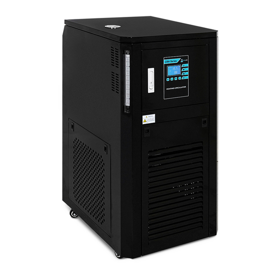
- Page 1 Recirculating Heater Manual Model: CRH Series CRH-30L, CRH-50L...
- Page 2 Index Safety Precautions and Explanations 1. Important Information 1.1 Safety Notices 1.2 Features 1.3 Technical Parameters 2. Diagrams 2.1 Hose Gaskets 2.2 Sight Glass 2.3 Back Panel 3. Control Panel Operation 3.1 LCD Display Operation 4. Installation 4.1 Thermal Transfer Fluids 4.2 Tubing Connections 4.3 Electrical Connection 4.4 Operating Area...
- Page 3 Safety Precautions and Explanations At USA Lab, safety is our number one priority. The following information provides guidelines for safety when using USA Lab equipment. Any piece of machinery can become dangerous to personnel when improperly operated or poorly maintained. ALL employees operating and maintaining USA Lab equipment should be familiar with its operation, thoroughly trained, and Instructed on the best safety practices.
- Page 4 Ensure that all power sources are turned off when the machine is not in use. This encompasses electrical and pneumatic power. • Read the manual for any special operational instructions for each piece of equipment. All USA Lab authored manuals are typically included with each device as well as posted online. •...
-
Page 5: Symbols And Warnings
Symbols and Warnings Below are examples of commonly used symbols and what they mean. Understand them and their potential consequences. -
Page 6: Section 1 | Important Information
Never use a generator to power this equipment. Do not change the length of the power cable. Repairs must be made by USA Lab or by instruction from USA Lab. If there is a problem, do not continue to use the heater. -
Page 7: Technical Parameters
1.2 Features • The CRH Series of high-performance closed loop recirculating heaters, use high wattage durable heating elements. • The magnetic drive pump can move your transfer fluid quickly and safely. • Casters aid in the portability of the heaters. - Page 8 Section 2 | Diagrams 2.1 Hose gaskets 2.2 Sight Glass...
- Page 9 2.3 Back Panel Only use water or water/glycol in the cooling loop Install the valve on the heater outlet...
-
Page 10: Section 3 | Control Panel Operation
Section 3 | Control Panel Operation 3.1 LCD Display Operation SV = Set temperature | PV = Current temperature To operate the heater Press the power button Press set and change the set value to your desired temperature Press the pump button Press the heating button Disclaimer –... -
Page 11: Section 4 | Preparing For Installation
Section 4 | Preparing for installation 4.1 Thermal Transfer Fluids Recommended: High performance silicone oil (Ambient – 300°C) Alternative: Propylene Glycol + Distilled Water | Ratio PG 10% : DW 90% (Ambient – 110°C) Alternative 2: Distilled Water Do Not Use Automotive Anti-freeze, it contains additives that have been known to corrode heat exchangers and remove the nickel plating. -
Page 12: Electrical Connection
4.3 Electrical Connection Each unit has its own power requirements, please understand their differences. This unit must be operated on its own circuit Installed by a licensed professional. Plugs: RH-30L | NEMA 6-20p (some early units shipped with L6-30p) RH-50L | NEMA L6-30p 4.5 Operating Instructions and Notes Only operate the unit in a climate-controlled facility. - Page 13 Priming instructions: • Power on the unit. • Open the ball valve. • Run the pump. • Wait for 30 minutes to allow the air bubbles to empty from the pump. • Then shut off the pump and close the ball valve. Operating notes: When using the unit always enable the pump first.
-
Page 14: Maintenance
5 | Maintenance Shut off the power switch AND disconnect the power cord before any maintenance. Use a damp soft cloth to wipe clean. Stubborn stains should be cleaned by neutral detergents. The maintenance of internal electrical and heating parts must be performed by professionals or trained electricians. - Page 15 Section 6 | Technical Diagrams and Troubleshooting 6.1 Circuit Board Diagrams Main Board Display Board...
-
Page 16: Troubleshooting
6.2 Troubleshooting Problem Cause Solution A. Plug unit in. B. Reset breaker in the front panel or at service A. Not plugged in. panel. B. No power supplied from outlet. C. Verify no power at circuit breaker in front No power C. - Page 17 Within this warranty period USA Lab will replace or repair components that fail due to manufacturer defect. For such repairs or parts, shipping charges will be covered in full or in part by USA Lab.
- Page 18 7.2 Return Policy We offer a 30-day return policy from when your package is delivered to your shipping address. By placing an order with USA Lab, you express that you have read and agreed to the following return policies. •...
- Page 19 This manual and its contents are subject to change without notice. USA Lab reserves the right of ultimate interpretation of the instruction manual. Additionally, USA Lab is not responsible for damages or injuries caused by improper use; knowingly or unknowingly.
Need help?
Do you have a question about the CRH Series and is the answer not in the manual?
Questions and answers