
Subscribe to Our Youtube Channel
Summary of Contents for Create PMD07
- Page 1 PMD07 motherboard Manual Create Flow s.r.o. Tel: 00420 722 712 652 info@createflow.cz www.createflow.cz...
- Page 2 7, warranty and after-sales service ............7 1, PMD07 motherboard introduction PMD07 board can control 57 stepper motors, is a highly integrated and reliable two-phase stepper motor driver board, start and stop by the external control and direction, 0.9-inch OLED blue screen shows the operating status Create Flow s.r.o.
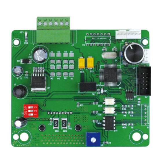
- Page 3 2, PMD07 motherboard wiring diagram J7: Motor interface and DC power interface Motor Interface: As shown above, the motor interface corresponds to the green line, red line, yellow line and blue line of the stepper motor from right to left.
- Page 4 The middle pin is a common terminal, short-circuited with "left", then the motor runs counterclockwise, short-circuit with "right" Motor running clockwise, you can connect the button switch control. J4: speed control knob interface Can be connected by external speed control knob Create Flow s.r.o. Tel: 00420 722 712 652 info@createflow.cz www.createflow.cz...
- Page 5 4, PMD07 main board features and features Power supply voltage DC 9-30 V, the maximum output current of 3.3A 232 communication, remote control Optional 0.9-inch OLED display...
- Page 6 5, PMD07 installation dimensions Unit (mm) Create Flow s.r.o. Tel: 00420 722 712 652 info@createflow.cz www.createflow.cz...
- Page 7 Product warranty for one year (excluding pump tube), during the warranty period as a result of improper operation or man-made damage, the Company is not responsible for the warranty. Over warranty repairs, only charge maintenance costs. Create Flow s.r.o. Tel: 00420 722 712 652 info@createflow.cz www.createflow.cz...
Need help?
Do you have a question about the PMD07 and is the answer not in the manual?
Questions and answers