Table of Contents
Advertisement
Available languages
Available languages
Quick Links
ELEKTRONICZNY REGULATOR PRĘDKOŚCI OBROTOWEJ
2021.03
DARCO Sp. z o.o.
POLAND, 39-200 Dębica, ul. Metalowców 43
tel. +48 14 680 90 00, fax +48 14 680 90 01
darco@darco.pl
darco.pl
INSTRUKCJA OBSŁUGI I MONTAŻU
INSTRUCTION MANUAL
ELECTRONIC MOTOR SPEED COTROLLER
/ KARTA GWARANCYJNA
ERO-32AP-0 V1.4
/ WARRANTY CARD
ERO-32AP-0 V1.4
PL
EN
Advertisement
Table of Contents

Subscribe to Our Youtube Channel
Related Manuals for Darco ERO-32AP-0 V1.4


Summary of Contents for Darco ERO-32AP-0 V1.4
- Page 1 INSTRUKCJA OBSŁUGI I MONTAŻU / KARTA GWARANCYJNA ELEKTRONICZNY REGULATOR PRĘDKOŚCI OBROTOWEJ ERO-32AP-0 V1.4 INSTRUCTION MANUAL / WARRANTY CARD ELECTRONIC MOTOR SPEED COTROLLER ERO-32AP-0 V1.4 2021.03 DARCO Sp. z o.o. POLAND, 39-200 Dębica, ul. Metalowców 43 tel. +48 14 680 90 00, fax +48 14 680 90 01 darco@darco.pl...
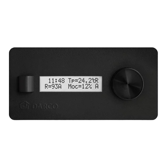
- Page 2 Regulator ERO-32AP-0 może służyć jako automatyczny lub manualny sterownik napięcie zasilania [V DC] 20 - 24 prędkości obrotowej urządzeń produkowanych przez firmę DARCO Sp. z o.o. moc znamionowa [W] Regulator wyposażony został w alfanumeryczny wyświetlacz LCD, na którym prezentowane są wszelkie niezbędne informacje. Wciskane pokrętło pozwala prąd maksymalny [mA]...
- Page 3 ELEKTRONICZNY REGULATOR PRĘDKOŚCI OBROTOWEJ ERO-32AP-0 V1.4 MENU Wyboru aktualnie prezentowanego ekranu informacyjnego dokonuje się za pomocą pokrętła (rys.1 poz.3) zgodnie z rysunkiem 3. Pierwsza linia wyświetlanego tekstu dla wszystkich ekranów jest zawsze taka sama i oznacza: numer ekranu informacyjnego wybrany tryb pracy: K6-K10 | zegar wybrany czujnik zewnętrzny:...
- Page 4 MENU MENU 1. PARAMETRY 1 Parametry Konfiguracja parametrów regulatora urządzenia sterowanego. 1.1 Tryb pracy 1.1 Tryb pracy CZUJNIK CYFROWY 1.2 Tryb czujnik.* Wybór trybu pracy regulatora: CZUJNIK ANALOGOWY czujnikowy - prędkość obrotowa urządzenia sterowanego zależy od 1.2.1 T(minimum) parametrów ustawionych w podmenu 1.2. Pozycja jest widoczna, gdy dokonano wyboru typu zewnętrznego czujnika w menu 2.2 - „analogowy”.
-
Page 5: Uruchomienie I Obsługa
ELEKTRONICZNY REGULATOR PRĘDKOŚCI OBROTOWEJ ERO-32AP-0 V1.4 2. USTAWIENIA 3. SERWIS Konfiguracja ustawień sterownika. Informacje serwisowe sterownika. 2.1 Typ urządzenia 3.1 Kod awarii Wybór typu urządzenia sterowanego (patrz tabela 1). Informacje o sytuacjach awaryjnych wykrytych przez sterownik (patrz 2.1.1 ANeco - Wybór typu urządzenia sterowanego z rodziny ANeco. - Page 6 SYGNALIZACJA SYTUACJI AWARYJNYCH Na ekranach informacyjnych sterownika oprócz najważniejszych danych i komunikatów (zgodnie z rysunkiem 3), znajdują się również dwie ikony powiadomień o awariach systemowych: · awaria zewnętrznego urządzenia (K14), · awaria wewnętrzna sterownika (K15). Każda usterka posiada własną flagę w kodzie awarii, dzięki której można w szybki sposób zdiagnozować potencjalny problem - tabele 2 i 3. Tabela 2.
-
Page 7: Warunki Gwarancji
ELEKTRONICZNY REGULATOR PRĘDKOŚCI OBROTOWEJ ERO-32AP-0 V1.4 GWARANCJA DARCO Sp. z o.o. udziela gwarancji na bezawaryjną pracę wyrobu zgodnie z warunkami techniczno-eksploatacyjnymi opisanymi w in- strukcji obsługi. WARUNKI GWARANCJI 1. Okres gwarancji wynosi 24 miesiące od daty zakupu towaru przez użytkownika (data musi być zgodna z datą wystawienia dowodu zakupu). - Page 8 The ERO-32AP-0 regulator may be used as an automatic or manual rotation spe- voltage [V DC] 20 - 24 ed controller with devices manufactured by DARCO Sp. z o.o. The regulator is nominal power [W] provided with an alphanumeric LCD display presenting all required information.
- Page 9 ELECTRONIC MOTOR SPEED COTROLLER ERO-32AP-0 V1.4 MENU The currently displayed information screen is selected using the knob (fig.1 item 3), as shown in Figure 3. The first line of the displayed text is always the same in all screens and designates as follows:...
- Page 10 MENU MENU 1. PARAMETERS 1 Parameters Parameter configuration of the controlled device regulator. 1.1 Operating mode 1.1 Operating mode DIGITAL SENSOR 1.2 Sensor mode* Selection of working mode of the regulator: ANALOG SENSOR sensing - the rotation speed of the controlled device depends on parameters 1.2.1 T(minimum) set in sub-menu 1.2.
-
Page 11: Start-Up And Operation
ELECTRONIC MOTOR SPEED COTROLLER ERO-32AP-0 V1.4 2. SETTINGS 3. SERVICE Settings of the controller. Service log of the controller. 2.1 Device type 3.1 Failure code Type selection for the controlled device (see Table 1). Information about malfunctions detected by the controller 2.1.1 ANeco - Selection of a controlled device of the ANeco family. -
Page 12: Maintenance
MALFUNCTION SIGNALLING In addition to the most important data and messages (as shown in Figure 3), the information screens also include icons signalling system malfunctions: · External device malfunction (K14), · Internal controller malfunction (K15). Each malfunction has its own flag in the malfunction code, enabling quick diagnosis of a potential problem - see tables 2 and 3. Table 2. -
Page 13: Warranty Conditions
ELECTRONIC MOTOR SPEED COTROLLER ERO-32AP-0 V1.4 WARRANTY DARCO Sp. z o.o. gives warranty for proper functioning of the device according to technical and operation conditions mentioned in this instruction manual. WARRANTY CONDITIONS 1. Warranty period is 24 months starting from date of purchase. - Page 14 KARTA GWARANCYJNA ELEKTRONICZNY REGULATOR PRĘDKOŚCI OBROTOWEJ ERO-32AP-0 V1.4 WARRANTY CARD ELECTRONIC MOTOR SPEED COTROLLER ERO-32AP-0 V1.4 TYP / TYPE: NR SERYJNY / SERIAL No: ERO-32AP-0 V1.4 kontrola jakości / quality control pieczęć sprzedawcy / seller stamp data produkcji / production date data sprzedaży / purchase date...
Need help?
Do you have a question about the ERO-32AP-0 V1.4 and is the answer not in the manual?
Questions and answers