Table of Contents
Advertisement
Quick Links
UM10789
USB-I²C-bus interface OM13518 with a GUI for the RTCs
PCF85263 and PCF85363
Rev. 1 — 19 May 2014
Document information
Info
Content
2
I
C-bus, computer control, GUI, RTC, PCF85263, PCF85363, USB
Keywords
User manual for the universal USB-I
Abstract
User manual
2
C-bus interface dongle OM13518
Advertisement
Table of Contents

Subscribe to Our Youtube Channel
Related Manuals for NXP Semiconductors OM13518

Summary of Contents for NXP Semiconductors OM13518
- Page 1 UM10789 USB-I²C-bus interface OM13518 with a GUI for the RTCs PCF85263 and PCF85363 Rev. 1 — 19 May 2014 User manual Document information Info Content C-bus, computer control, GUI, RTC, PCF85263, PCF85363, USB Keywords User manual for the universal USB-I...
- Page 2 UM10789 NXP Semiconductors USB-I²C-bus dongle OM13518 with a GUI Revision history Date Description 20140519 first revision Contact information For more information, please visit: http://www.nxp.com For sales office addresses, please send an email to: salesaddresses@nxp.com UM10789 All information provided in this document is subject to legal disclaimers.
-
Page 3: Introduction
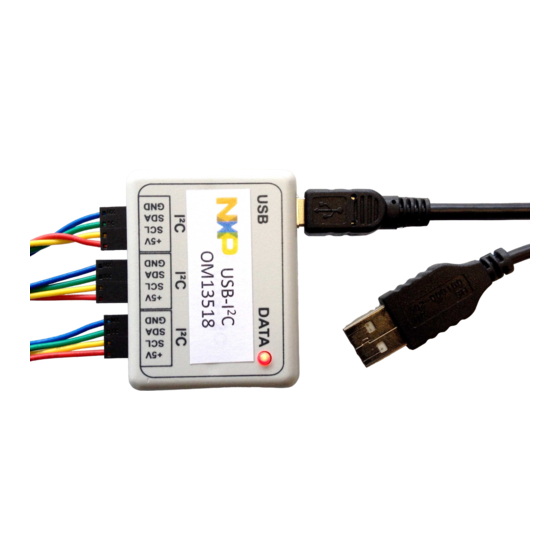
USB-I²C-bus dongle OM13518 with a GUI 1. Introduction The OM13518 dongle is an easy to use interface handler between the USB of a PC and the I C-bus. The software control via a Graphical User Interface (GUI) allows a fast start to communicate with different circuits. -
Page 4: Fig 1. Simplified Block Diagram Of The Om13518
UM10789 NXP Semiconductors USB-I²C-bus dongle OM13518 with a GUI 3. Dongle 3.1 Circuit diagram The dongle establishes the connection between the PC (USB port) and the I C-bus interface. Fig 1. Simplified Block diagram of the OM13518 3.2 Interfacing I... -
Page 5: Fig 2. Interfacing To The I C-Bus
UM10789 NXP Semiconductors USB-I²C-bus dongle OM13518 with a GUI In case that the periphery is connected to the +5V from the OM13518 no V connection must be used. Fig 2. Interfacing to the I c-bus There is no need for external pull-up resistors, since 10 kΩ pull-ups are already built in the OM13518 dongle. -
Page 6: Fig 4. Start Window Of The Gui
C-bus cable to your application; turn on the power in case an external one is needed. 2. The red LED will light up to indicate that the OM13518 successfully started up. 3. Now the system is ready for starting the GUI software 4.2 GUI Installation... -
Page 7: Fig 5. First Tab: Usb-I2C Commands
UM10789 NXP Semiconductors USB-I²C-bus dongle OM13518 with a GUI 5. Features of the Graphical User Interface (GUI) The GUI can be used as a universal I C-bus interface for controlling any peripheral circuit. Alternatively some specific windows are available e.g. for the Real-Time Clocks PCF85263 and PCF85363. -
Page 8: Fig 6. Hovering The Mouse-Pointer And Drop-Down Menus
UM10789 NXP Semiconductors USB-I²C-bus dongle OM13518 with a GUI 6. Tabs on the GUI of the RTCs: PCF85263, PCF85363, to follow 7. Hovering the mouse-pointer over a function button, tool tips will pop up for explanations. 8. Pressing▼ will open the list of possible options to select from. -
Page 9: Fig 7. Window Structure; Time, Alarms, Timestamps
UM10789 NXP Semiconductors USB-I²C-bus dongle OM13518 with a GUI Fig 7. Window structure; Time, Alarms, Timestamps 5.2.1 Save and read back the configuration 5.2.1.1 All the setting can be saved 1. Work with the GUI until you have the IC configured as desired. -
Page 10: Fig 8. Selecting The Directory
UM10789 NXP Semiconductors USB-I²C-bus dongle OM13518 with a GUI Fig 8. Selecting the directory 3. If the GUI succeeds in writing the file, it will produce a pop-up window and then just press OK (see Fig 9). Fig 9. Confirmation window UM10789 All information provided in this document is subject to legal disclaimers. -
Page 11: Fig 10. Xml Format Example
UM10789 NXP Semiconductors USB-I²C-bus dongle OM13518 with a GUI File Format: The file is written in standard XML format, which almost all Operating Systems can read (see Fig 10). Fig 10. XML format example 5.2.1.2 Reload the settings 1. Read back a saved configuration file with Read Configuration (see Fig 11): Fig 11. -
Page 12: Fig 12. Confirmation Window
UM10789 NXP Semiconductors USB-I²C-bus dongle OM13518 with a GUI 2. If the GUI manages to read in the files successfully, it will produce a pop-up window and then just press OK (see Fig 12). Fig 12. Confirmation window 5.3 Examples 5.3.1 Setting the clock and reading it... -
Page 13: Fig 14. Time Control
UM10789 NXP Semiconductors USB-I²C-bus dongle OM13518 with a GUI • START will continuously read the time at about once every second (see Fig 7 and Fig 14). There are options to change from 24 hour to 12 hour mode, activate the 1/100s resolution and change the RTC from RTC mode (clock mode) to stop watch mode (see Fig 7 and Fig 14). -
Page 14: Fig 16. Enable The Inta For Interrupt Mode
UM10789 NXP Semiconductors USB-I²C-bus dongle OM13518 with a GUI 2. Enable INTA for interrupt mode (see Fig 16). Fig 16. Enable the INTA for interrupt mode 3. Enable INTA for Watchdog (pulse at each time countdown occurs) (see Fig 17). -
Page 15: Fig 18. Enable The Watchdog For A Repeat Every 2 Seconds
UM10789 NXP Semiconductors USB-I²C-bus dongle OM13518 with a GUI 4. Enable the watchdog for a repeat every 2 seconds for example (see Fig 18). Fig 18. Enable the watchdog for a repeat every 2 seconds 5. Observe the LED flashing every 2 seconds!!! 5.3.3 Interactive quartz frequency offset correction:... -
Page 16: Dedicated Drop Down Menus Are Integrated For E.g
UM10789 NXP Semiconductors USB-I²C-bus dongle OM13518 with a GUI 5.3.4 Dedicated drop down menus are integrated for e.g.: • Register overview: reading all the values at once • Back-up battery control • Timestamp • Watch dog • RAM UM10789 All information provided in this document is subject to legal disclaimers. -
Page 17: Legal Information
In no event shall NXP Semiconductors be liable for any indirect, incidental, Evaluation products — This product is provided on an “as is” and “with all punitive, special or consequential damages (including - without limitation - faults”... -
Page 18: Table Of Contents
UM10789 NXP Semiconductors USB-I²C-bus dongle OM13518 with a GUI 7. List of figures Fig 1. Simplified Block diagram of the OM13518 ..4 Fig 2. Interfacing to the I c-bus ........5 Fig 3. A) Dongle OM13518, B) connected to an evaluation board .......... -
Page 19: Contents
UM10789 NXP Semiconductors USB-I²C-bus dongle OM13518 with a GUI 8. Contents Introduction ............3 Key features ............3 USB-I C interface module ........3 Software ............. 3 Dongle ..............4 Circuit diagram ........... 4 Interfacing I C-bus peripherals ......4 Installation ............
Need help?
Do you have a question about the OM13518 and is the answer not in the manual?
Questions and answers