
Subscribe to Our Youtube Channel
Related Manuals for Actisense PRO-BUF-2


Summary of Contents for Actisense PRO-BUF-2
- Page 1 Intelligent Type Approved NMEA Buffer - PRO-BUF-2 Connect without limits Professional Type Approved NMEA 0183 Buffer ® Install/User Manual Issue 1.09 Page 1 © 2018 Active Research Limited...
-
Page 2: Important Notices
Actisense products are intended for use in a marine environment, primarily for below deck use. If a product is to be used in a more severe environment, such use may be considered misuse under the Active Research Ltd guarantee. -
Page 3: Installation Warnings
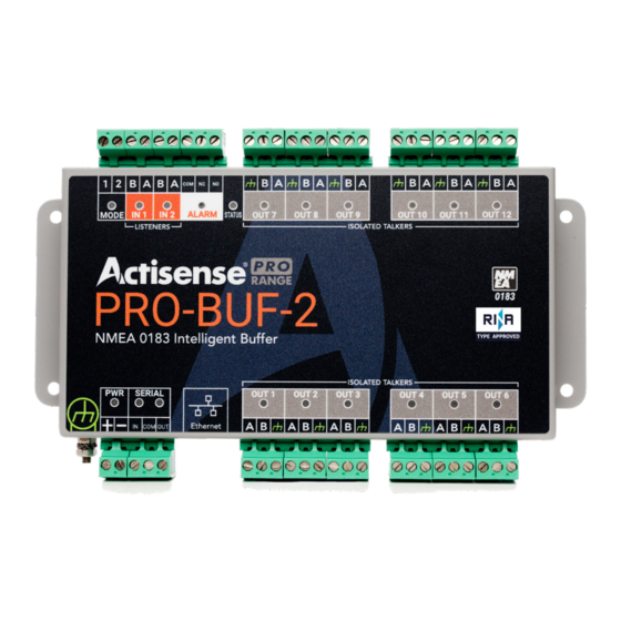
Intelligent Type Approved NMEA Buffer - PRO-BUF-2 Features Introduction The PRO-BUF-2 is designed to suit the majority of NMEA 0183 systems and ready to go ‘out of the box’ by simply • 2 x NMEA 0183 OPTO-isolated inputs hard-wiring the two mode inputs as required. The manually configurable basic modes of operation include variations •... - Page 4 Connecting to NMEA Devices The ‘A/+’ and ‘B/-’ of the NMEA 0183 device should be matched to the ‘A’ and ‘B’ on the PRO-BUF-2. If the NMEA 0183 device has a ground (GND) wire (and no ‘B/-’ wire), simply connect this to ‘B’ on the PRO-BUF-2.
-
Page 5: Din Rail Mounting
Attach the PRO-BUF-2 to the DIN rail as shown in the diagrams below. Ensure the PRO-BUF-2 sits flush against the DIN kit clips, and that the rail clips are securely fastened to the DIN Rail.* Insert the RJ45 plug in to the PRO-BUF-2 ‘Ethernet’ terminal until a click is heard. To remove the RJ45 plug, push down on the locking clip and pull the cable away from the ‘Ethernet’... - Page 6 Standard Ethernet Networks For a list of modes and how to set them up, refer to the ‘Mode Table’ sheet included with the PRO-BUF-2 or available If the PRO-BUF-2 is connected to an Ethernet network containing both DHCP and DNS servers, launch any from the PRO-BUF-2 ‘Downloads’...
-
Page 7: Troubleshooting Guide
First level PRO-BUF-2 diagnostics / fault finding can be performed by observing the LED behavior. The normal behav- ior of the PRO-BUF-2 LEDs is described below. If the LEDs are not behaving as expected, this will indicate a fault in either the device connected to the PRO-BUF-2, the wiring/connections, or the PRO-BUF-2 itself. -
Page 8: Technical Specification
Kit of 2 clips & 4 screws. Use with top hat Host Interface DIN-KIT-1 If the Actisense support engineer concludes that the PRO-BUF-2 unit should be returned to Actisense, a detection (EN 50 022) or G section (EN 50 035) rails ‘Return Merchandise Authorisation’... - Page 9 Connect without limits Active Research Ltd 21 Harwell Road Poole, Dorset UK, BH17 0GE Telephone: +44 (0)1202 746682 Email: sales@actisense.com Web: www.actisense.com ®...
Need help?
Do you have a question about the PRO-BUF-2 and is the answer not in the manual?
Questions and answers