Advertisement
Quick Links
Interface Manual
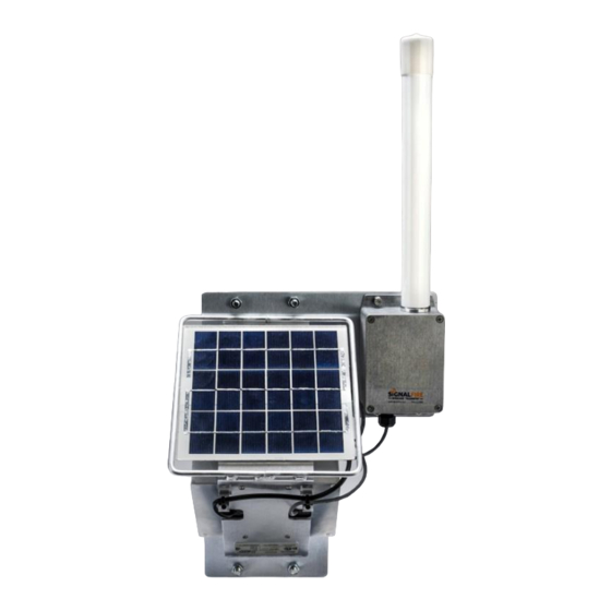
Solar Powered Repeater
The SignalFire Solar powered repeater is a stand-alone device with the following features:
-
Long Range (2-3 miles) 500mW Radio
-
Integrated high gain omni-directional antenna or remote antenna options
-
Automatically forwards messages from other SignalFire Nodes
-
Mounting bracket and U-Bolts to mount to a vertical or horizontal pole
-
AES 128bit Encryption
Rev 2.0
SignalFire Model: Repeater-xxxx
SignalFire Telemetry
1
Advertisement

Summary of Contents for SignalFire Repeater Series
- Page 1 Interface Manual Solar Powered Repeater SignalFire Model: Repeater-xxxx The SignalFire Solar powered repeater is a stand-alone device with the following features: Long Range (2-3 miles) 500mW Radio Integrated high gain omni-directional antenna or remote antenna options Automatically forwards messages from other SignalFire Nodes...
-
Page 2: Specifications
Integrated HC Solar system includes 4W solar panel, integrated charger and 9Ah battery pack Temperature Rating -40°C to +85°C Radio 500mW 902-928MHz Ism Band, FHSS radio Antenna Integrated omni-directional antenna or N-Connector for external SignalFire antennas Compliance FCC/IC Certified. FCC ID: W8V-SFTS500, IC: 8373A-SFTS500 SignalFire Telemetry Rev 2.0... -
Page 3: Connections And Components
Run the power cable from the solar system through the cord grip and plug into this connector. Tighten cord grip to ensure water tight seal Configuration Port Connect a SignalFire USB-Serial-4PIN cable to this port to configure the Repeater with the SignalFire ToolKit software SignalFire Telemetry... - Page 4 Radio encryption setting Unique Modbus ID Node Name (optional) All settings are made using the SignalFire Toolkit PC application and a serial programming cable (USB-Serial- 4PIN). Using the SignalFire Toolkit The SignalFire Toolkit application can be downloaded at www.signal-fire.com/customer. After installation, launch the software and the main toolkit window will open: Select the COM port associated with the Repeater and click “Auto-Detect Device on COM Port.”...
- Page 5 ❶ COM Settings ❹ Register Values ❷ Node Information ❸ Radio and Device Settings SignalFire Telemetry Rev 2.0...
- Page 6 ID to report its status registers to the Gateway Node Name This optional field will be reported to the Gateway and will be visible with the SignalFire Toolkit and can be used to identify the Repeater. Operating Mode The Repeater will automatically act as a repeater in the SignalFire network and forward messages for other devices.
- Page 7 Repeater enclosure through the cord grip and plug into the battery connector. Tighten the cord grip to ensure a water-tight seal. Mount the solar panel with a clear view of the southern sky. SignalFire Telemetry Rev 2.0...
- Page 8 In addition to forwarding messages for other devices, the Repeater also reports status registers to the SignalFire Telemetry Modbus Gateway. The data that is sent to the gateway is available at the gateway in registers where it can then be read by a Modbus RTU.
- Page 9 Revision History Revision Date Changes/Updates 12/16/21 Updated for current repeater hardware revision. Reformatting SignalFire Telemetry Rev 2.0...
- Page 10 APPENDIX - FCC and IC Statements Changes or modifications not expressly approved by SignalFire Telemetry, Inc could void the user’s authority to operate the equipment. This device complies with Part 15 of the FCC Rules. Operation is subject to the following two conditions: (1) this device may not cause harmful interference, and (2) this device must accept any interference received, including interference that may cause undesired operation.
Need help?
Do you have a question about the Repeater Series and is the answer not in the manual?
Questions and answers