
Related Manuals for Novametrix Medical Systems TIDAL WAVE 610


Summary of Contents for Novametrix Medical Systems TIDAL WAVE 610
- Page 1 HAND-HELD CAPNOGRAPHY MONITOR Service Manual Model 610 April 17, 2000 Catalog No. 6700-90-01 Novametrix Medical Systems Inc. PO Box 690 5 Technology Drive Wallingford, Connecticut, U.S.A. 06492...
-
Page 3: Table Of Contents
Contents Safety ..................... 1 Introduction ................... 3 Indication for use .................. 3 Operational Overview ................3 Configuration Menu ..............4 Theory of Operation ................7 2738 Main Board .................. 7 System Memory ................. 10 Serial Communications .............. 10 User Interface Control Circuitry ..........11 Real Time Clock, Power on RESET Generation and Glue Logic .. - Page 4 Battery Indicator ................. 31 Rechargeable Batteries ............. 31 AA Lithium Batteries ..............32 AC wall adapter/charger (External DC supply) ......32 Removing and installing the battery ........... 33 Assembly Exchanges ................. 33 Disassembling the Monitor ............33 Reassembling the monitor ............36 Serial Communications/Power Interface Connector ......
- Page 5 Copyright 1998, 2000 Novametrix Medical Systems Inc. This document contains information which is proprietary and the property of Novametrix Medical Systems Inc., and may not be reproduced, stored in a retrieval system, translated, transcribed, or transmitted, in any form, or by any means, without prior explicit written permission from Novametrix Medical Systems Inc.
- Page 6 17-Apr-00 Service Policy Novametrix Medical Systems Inc. will provide Warranty Service Support to its customers within 48 hours of receiving a telephone request for technical support. This 48 hour period begins once a service request is placed through the Factory Technical Support Department in Wallingford, Connecticut.
-
Page 7: Safety
Section 1 Safety TIDALWAVE handneld capnograph is electrically isolated. Patient leakage current flowing from the instrument to ground is limited to less than 100 uA. For maximum patient and operator safety, you must follow the following warnings and cautions. WARNINGS Indicates a potentially harmful condition that can lead to personal injury. - Page 8 Section 1 NOTES Indicates points of particular interest or emphasis for more efficient or convenient operation. • The Tidal Wave monitor is intended for operation with Novametrix Single Patient Use airway adapters. • Certain rebreathing circuits, or the presence of artifact such as cardiogenic oscillations, may cause the monitor to react to non-respiratory CO fluctuations as if they were breaths.
-
Page 9: Introduction
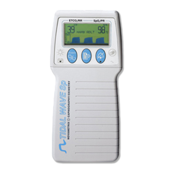
Section 2 Introduction The TIDAL WAVE hand-held capnograph from Novametrix is designed to monitor CO whenever capnography is required. The monitor combines full graphics capabilities, a no-respiration alert and rugged CAPNOSTAT CO sensor technology. 2.1 Indication for use The TIDAL WAVE capnograph is a hand-held non-invasive CO monitor specifically designed for short term monitoring during transport, emergency, anesthesia, post anesthesia recovery, respiratory care and intensive care. -
Page 10: Configuration Menu
Section 2 Operational Overview Indicators Function/Meaning Green; battery is fully charged. Slow flashing yellow; battery power is low. Fast flashing red; battery is exhausted (10 - 15 minutes monitor time left). Illuminated when "external" power is connected. Steady yellow: audio silenced for 2 min., no alert in progress. Flashing yellow: audio silenced (no alert in progress). - Page 11 Section 2 Operational Overview Press the Alert key to change the setting of the selected column. Press the NEO key to exit the CONFIGURATION menu and return to normal monitoring mode (selections will be saved). Displays selected setting Selects column Changes settings of selected column Press to set time/date...
- Page 12 Section 2 Operational Overview [This page intentionally blank.] Model 610 Service Manual Rev. 01...
-
Page 13: Theory Of Operation
Section 3 Theory of Operation The TIDAL WAVE is a microprocessor-based handheld instrument that measures the clinical parameters of CO production and respiration rate. The system contains all the circuitry necessary for displaying patient information gathered from the CAPNOSTAT® sensor. The theory of operation of the TIDAL WAVE is explained in detail in the subsections that follow. - Page 14 Section 3 2738 Main Board The maximum operating frequency of the integrated processor is 16.78 MHz. The operating frequency is software selectable and generated by an internal VCO operating from Y1, a 32.768KHz watch crystal. The Timing Processor Unit (TPU) co-processor of the MC68332 provides timing generation derived from the system clock.
- Page 15 Section 3 2738 Main Board and all system functions have been set, the LED output toggles at a 1Hz rate switching transistor Q3 which drives the status LED D3, indicating that the system is ready for operation. Table 3. Chip Select, Control and Discrete I/O System Signal Port Pin Functions...
-
Page 16: System Memory
Section 3 2738 Main Board Table 3. Chip Select, Control and Discrete I/O System Signal Port Pin Functions Comments Name D9 pulled low, Discrete I/O on power-up MODCK / Port F0 LED CPU Activity Indicator IRQ1* / Port F1 AUD_EN Audio Enable Signal Case Heater Over Temperature Shut IRQ2* / Port F2... -
Page 17: User Interface Control Circuitry
Section 3 2738 Main Board logic level signals and are diode protected against over voltage by D38 and D35 should IC29 breakdown from ESD. Refer to the table below for the pinout of J101. Table 4: Power/Communications 6-pin modular connector J101 (rear panel). Pin Number Signal Function... -
Page 18: Real Time Clock, Power On Reset Generation And Glue Logic
Section 3 Real Time Clock, Power on RESET Generation and Glue Logic 3.2 Real Time Clock, Power on RESET Generation and Glue Logic Reference sheet 2 on schematic. Timekeeping for date, and time stamping of patient trend information, is provided by IC9. This device contains a built-in crystal for precise time and date measurement. - Page 19 Section 3 CO2 System Analog Subsections When current flows through the source, it will also flow through current sensing resistor R110, creating a differential voltage proportional to the source current: = (V ) * R where V = voltage out of difference amplifier V(DA) proportional to current through the source element = 24V +/- 0.625V...
-
Page 20: Capnostat Case And Detector Heater Control
Section 3 Capnostat Case and Detector Heater Control 3.4 CAPNOSTAT Case and Detector Heater Control Refer to schematic page 4. The temperature of the system directly affects its ability to accurately measure CO and therefore must be precisely maintained at a controlled value. Two separate heaters and control circuitry are used; one regulates the temperature of the detectors for the CO Data and Reference channels;... -
Page 21: Co2 Input Signal Path
Section 3 CO2 Input Signal Path 3.5 CO2 Input Signal Path Refer to schematic page 5. The signals from the sensor CO2DATAIN (CO Data) and CO2REFIN (Reference Signal) have similar signal paths. The CO2DATAIN passes through a high pass filter with a gain of 3.8 consisting of C70, R164 and buffer amplifier IC25B. -
Page 22: Power Supply And Battery Charger
Section 3 Power Supply and Battery Charger 3.7 Power Supply and Battery Charger Supply and Reference Voltage Generation (refer to schematic sheet 7). The monitor operates from either an isolated DC Mains power or from the internal Battery. There are two options presently for the internal battery, a Nickel Metal Hydride Battery Pack (NiMH), or a High Energy Lithium Cell Pack. -
Page 23: 2737 Board
Section 3 Power Supply and Battery Charger Table 5: Power Supply and Reference Outputs Signal Supply CVREF +2.5VDC Buffered reference for the A/D Converter. Buffered reference used in the CAPNOSTAT heater control circuitry. 2CVREF +5.0VDC -2CVREF -5.0VDC Buffered reference used for the contrast control circuitry. VREFO/2 +1.25VDC Buffered reference used for DC excitation for the barometric pressure sensor. - Page 24 Section 3 Power Supply and Battery Charger R9 keeps D10 operating in the knee region and C5 and C7 provide filtering. Over current protection is provided by F1, a 1A slo-blo replaceable fuse. Reverse leakage protection is provided by D5 and D6 which prevents the battery from trying to power BVDD and +VCHG in the battery operation state.
-
Page 25: Functional Tests
Section 4 Equipment Required Section 4 Functional Tests The Functional Test described below verifies overall functional integrity of the monitor and sensor. If the TIDAL WAVE monitor does not pass these tests, remove from use and contact the Novametrix Service Department for repair/replacement assistance. - Page 26 Section 4 Procedure Verify the unit displays error then “CHECK ADAPTER” at the top of the display. Connect the Disposable Adult Airway Adapter PN: 6063-01 to the CAPNOSTAT. Breathe into the airway adapter and verify both the readings and the waveform displayed on the computer are acceptable.
-
Page 27: Accuracy Tests
Section 5 Equipment Required Section 5 Accuracy Tests The Accuracy Test verifies the performance accuracy of the Model 610. This test is typically performed in conjunction with (after) the Functional Tests described on page 19. If the monitor does not pass the accuracy test, remove from use and contact the Novametrix Service Department for repair/replacement assistance. - Page 28 Section 5 Test Procedure Press and hold the key until the monitor displays the "Zero/Verify" menu. Press key to enter the "Verify" menu. The instantaneous value should be .4 (+.5 -.4 torr). The value may take a few seconds to stabilize. NOTE While the zero calibration is in process there should be no CO in the immediate area of...
- Page 29 Section 5 Test Procedure CTMP 45.00 ± 0.2 °C DTMP 45.00 ± 0.2 °C DCHN 3600 ± 200 A/D counts RCHN 3600 ± 200 A/D counts Press the key to exit, then press the key to power down the monitor. This completes the Accuracy Tests for the Model 610.
- Page 30 Section 5 Test Procedure [This page intentionally blank.] Model 610 Service Manual Rev. 01...
-
Page 31: Electronic Tests
Section 6 Electronic Tests The Electronic Tests verify the calibration and operation of the electronic circuits within the Model 610. These tests DO NOT need to be performed on a regular (preventative) basis. Perform these tests only if the monitor fails to operate as expected or fails the Accuracy Tests or the Functional Tests. The Electronic Tests should be performed only by qualified service personnel. - Page 32 Section 6 Test Procedure Measure the following voltages on the 2738 board. Use TP 12 as ground reference. Refer to the illustration for test point locations. Signal Name Location Voltage Tolerance TP 17 feed through 5.00 V ± 100 mV + VA D26 cathode + 13.75 V...
- Page 33 Section 6 Test Procedure Enter the configuration menu by pressing and holding the NEO key immediately followed by the backlight / contrast key. Press the backlight / contrast key four times to display the engineering screen. ± Verify the CTMP and DTMP rise and stabilize to 45.00 °C 0.1 °C.
-
Page 34: Safety Testing
Section 6 Safety Testing 6.3 Safety Testing Using a leakage test fixture, and with the external AC adapter/charger connected, measure the leakage current: • Normal • Normal reverse ground • Normal ungrounded Verify a leakage current <50 uA. Model 610 Service Manual Rev. -
Page 35: Maintenance
Section 7 Maintenance 7.1 General This section presents recommended maintenance schedules for the Model 610 and information on general maintenance, such as battery and fuse replacement, disassembly and assembly instructions, and system software updates. 7.2 Maintenance Schedules The electronic circuits within the Model 610 hand-held capnograph monitor do not require scheduled calibration or service. -
Page 36: Cleaning And Sterilization
Section 7 Cleaning and Sterilization 7.3 Cleaning and Sterilization Follow the cleaning and sterilization instructions listed below to clean and/or sterilize the monitor and its accessories. CAUTION The airway adapter is designed for single patient use. Sterilizing may affect system performance. 7.3.1 Monitor •... -
Page 37: Battery Indicator
Section 7 Battery and AC Operation 7.4.1 Battery Indicator While running on battery power, a battery life indicator will illuminate green for a charged battery, slowly flash yellow for a battery getting low, and quickly flash red when only a few minutes remain. The audio will sound during the flashing red condition, and for safety reasons, cannot be silenced. -
Page 38: Aa Lithium Batteries
Section 7 Battery and AC Operation 7.4.3 AA Lithium Batteries To power TIDAL WAVE from AA lithium batteries, insert seven disposable batteries (Energizer L91 or equivalent see Accessories on page 45) into the optional Battery Case (Cat. No. 6862-00) following the polarity markings on the case. -
Page 39: Removing And Installing The Battery
Section 7 Assembly Exchanges 7.4.5 Removing and installing the battery Grasp the finger grips on each end of the battery cover. Squeeze together and pull so that the cover opens to reveal the internal battery (the cover is hinged on the bottom of the case). Remove the rechargeable battery or the lithium battery case from the monitor. - Page 40 Section 7 Assembly Exchanges Turn the monitor upside down and remove the four cover screws from the bottom cover. cover screws Carefully lift the rear cover from the monitor. The separate assemblies of the monitor can now be removed. Lift the Main Board and disconnect ribbon cable from the Sensor Assembly Board by grasping the connector (not the cable) and gently rocking from side to side to loosen.
- Page 41 Section 7 Assembly Exchanges To disconnect ribbon cable J3, grasp the edge of the ZIF (zero insertion force) connector with one forefinger on either side. Pull gently sideways to release the mechanism. Slide the ribbon cable out. ZIF connector ribbon cable Remove four screws from the Sensor Assembly Board.
-
Page 42: Reassembling The Monitor
Section 7 Serial Communications/Power Interface Connector Remove 4 screws holding the Display Board in place. Do not bend the tabs on the board, the LCD display can not be removed from the board. Be sure not to lose the plastic bezel located in between the LCD display and the display window. display board screws ribbon cable... -
Page 43: Software Update Instructions
Section 7 Software Update Instructions 7.7 Software Update Instructions The following procedure is for updating the monitor’s software from a supplied Software TIDAL WAVE Update Kit using an IBM-compatible computer and the Base Station (Cat. No. 6998-00). Refer to any instructions that may accompany the software update diskettes for changes in the procedure or other pertinent information. - Page 44 Section 7 Software Update Instructions If you are not sure of the process, press any other key and call service or Novametrix Service Department at 1-800-243-3444, in Connecticut call collect (203) 265-7701. Turn the TIDALWAVE on (connect the AC adapter/charger to the base station if the battery is not fully charged).
-
Page 45: Display Status Messages
Section 8 Display Status Messages System Messages Shown below is a list of system messages that the Model 610 may display during normal operation. See “Status Messages and Codes” on page 41 and “Battery Status and Alerts” on page 41 for other messages. Message Meaning of message ZRO: HOLD... - Page 46 Section 8 Message Meaning of message WAVEFORM SPEED: Configuration menu parameter and options. Refers to the sweep SLOW speed on the capnograph waveform. MEDIUM FAST NO RESP TIMEOUT: Configuration menu parameter and options. A NO RESPIRATION 20 sec. alert will sound after 20, 40 or 60 seconds (depending upon setting 40 sec.
-
Page 47: Battery Status And Alerts
Section 8 Battery Status and Alerts Battery Status and Alerts LED on the front panel flashes when the battery is extremely low; this will be accompanied by an audible alert. When this occurs connect the AC adapter to the monitor, and connect to an AC power source. - Page 48 Section 8 Battery Status and Alerts Trian- Message Description Check adapter or select correct adapter type (adult/neonatal). To change adapter, wrong adapter (not single patient use), CHECK ADAPTER contaminated or obstructed airway adapter window, or obstructed airway adapter. Measured CO is negative.
-
Page 49: Specifications
Section 9 Specifications 9.1 Monitor Specifications Below are specifications for the Novametrix TIDAL WAVE hand-held capnograph. These specifications are listed for informational purposes only, and are subject to change without notice. 9.1.1 Physical • Size: 7.9” x 3.25” x 1.5”, Weight: 24 ounces. •... -
Page 50: Symbol Descriptions
Section 9 Monitor Specifications 9.1.3 Symbol Descriptions The following International Electrotechnical Commission (IEC) symbols appear on the TIDAL WAVE and its accessories: Patient Isolation - identifies patient isolation type as BF. Attention - Consult manual for detailed information. Recycle or dispose of batteries in accordance with local law. Model 610 Service Manual Rev. -
Page 51: Accessories
Section 10 Accessories Capnography Monitor TIDAL WAVE Model 610 The table below is a list of accessories for the TIDAL WAVE Hand-Held Capnograph, Model 610 (Cat. No. 6700-00). Catalog No. Description 6063-00 Pediatric/Adult Single Patient Use airway adapters (box of 10) 6421-00 Pediatric/Adult Single Patient Use airway adapters with mouthpiece (box of 10) 6421-25... - Page 52 Section 10 [This page intentionally blank.] Model 610 Service Manual Rev. 01...
-
Page 53: Parts
Section 11 Parts 6700-00 TIDAL WAVE Hand-Held Capnograph, Model 610 Line No. Part No. Description 0001 2738-01 MAIN BOARD ASSY, MODEL 610 0002 6680-13 BOTTOM COVER W HOLE AND SHIELDING, HAND HELD 0003 6685-16 BATTERY DOOR, HAND HELD ENCLOSURE 0004 6768-27 MEMBRANE KEYPANEL, MODEL 610 0005... - Page 54 Section 11 2738-17 Main Board Subassembly Part No. Description 130015 TRANSDUCER, AUDIO, 2400 HZ, 12V, 40MA, .5 DIA 152085 CAPACITOR, 1500UF, 16V, AL ELCTLT, RADIAL, .3 152096 CAPACITOR, 220UF, 35V, 20%, ELCTLT, 8X10.8 CA 154072 CAPACITOR, .1UF, 50V, 10%, X7R, CER CHIP, S M 154079 CAPACITOR, 10UF, 25V, 10%, TANTALUM, SURFACE MOUNT 154086...
- Page 55 Section 11 Part No. Description 474225 RESISTOR, 499 OHM, 1/16W, 1%, 0603 STYLE, SURFACE MOUNT 474227 RESISTOR, 1K OHM, 1/16W, 1%, 0603 STYLE, SURFACE MOUNT 474229 RESISTOR, 2.05K OHM, 1/16W, 1%, 0603 STYLE, SURFACE MOUNT 474230 RESISTOR, 3.32K OHM, 1/16W, 1%, 0603 STYLE, SURFACE MOUNT 474231 RESISTOR, 4.99K OHM, 1/16W, 1%, 0603 STYLE, SURFACE MOUNT 474233...
- Page 56 Section 11 Part No. Description 483019 TRANSISTOR, MMBT2907ALT1, PNP, SOT-23, SURFACE MOUNT 484060 TRANSISTOR, MMBT3904T, NPN, SURFACE MOUNT 484562 IC, LT1175CS8-ADJ, MICROPOWER REGULATOR, 8 P 484563 IC, LT1117CST, VOLTAGE RGLTR, POS, ADJ, 3 P 484567 VOLTAGE REGULATOR, LT1372CS8, 35V, 8 PIN, SURFACE MOUNT 484569 VOLTAGE REGULATOR, LT1375CS8-5, 8 PIN, SURFACE MOUNT 485532...
- Page 57 Section 11 Part No. Description Line 0001 IC, LT1490CS8, RAIL TO RAIL OP AMP, 8 PIN 486823 6808-17 Transducer Assembly, CAPNOSTAT III Line No. Part No. Description 0001 2737-01 INTERFACE BOARD ASSY, MODEL 610 0002 6808-09 OVERALL WIRING DIAGRAM, TRANSDUCER 0003 6809-17 CABLE PREPARATION, MODEL 610...
- Page 58 Section 11 Part No. Description 180022 INDUCTOR, 10UH, 10%, SURFACE MOUNT 180030 INDUCTOR-CAP, 4700PF, 50VDC, 2A, 3 TERM, SURFACE MOUNT 180034 FERRITE FILTER, 4 LIN, EMI SUPPRESSION 180035 FERRITE FILTER, 8 LINE, EMI SUPPRESSION 180046 INDUCTOR, 18UH @ 2.5M HZ, +25% -15%, SURFACE MOUNT 211514 CONNECTOR, 5 PIN, HEADER, RT ANGLE, .1 SP 211639...
- Page 59 Section 11 Part No. Description 486820 IC, BQ2004SN, FAST CHARGE, 16 PIN, SURFACE MOUNT 515085 FUSE W FUSEHOLDER, 2A, 125V, SLO-BLO, SUBMIN 515087 FUSE W FUSEHOLDER, 1A, 125V, SLO-BLO, SUBMIN 2739-01 Battery & Comm Interface Board Assembly Line No. Part No. Description 0001 2739-02...
- Page 60 Section 11 [This page intentionally blank.] Model 610 Service Manual Rev. 01...
-
Page 61: Drawings And Schematics
Section 12 Drawings and Schematics Hand-Held Capnography TIDAL WAVE Model 610 Below is a list of schematics and drawings for the TIDAL WAVE Hand-Held Capnograph, Model 610 (Cat. No. 6700-00). Drawing No. Code Description Sheets 6700 Overall Wiring Diagram 6700 ETCO2 Monitor, Model 610 - TIDAL WAVE 6700 Main Assembly, Model 610 - TIDAL WAVE...
Need help?
Do you have a question about the TIDAL WAVE 610 and is the answer not in the manual?
Questions and answers