
Summary of Contents for GHIELMETTI GKV 2x11x14 621 SS K
- Page 1 Tripping matrix for Generator Protection Systems GKV 2x11x14 621 SSK (7UW50) – 250 VDC Part. No. 674.114.913.02 Manual Edition 04/2020...
-
Page 2: Table Of Contents
14.2 Back view ..................................15 14.3 Side view ..................................16 15 Specifications ..................................17 16 Ordering Data ..................................18 17 Service condition and repairs ............................18 17.1 Replace the mini-fuse ..............................18 GHIELMETTI AG – 7UW50 - Technische Dokumentation ROR/09.02.2021 Page 2 of 19... -
Page 3: Conformity
We are convinced that your choice will prove to be a wise and worthy decision for many years to come. Your GHIELMETTI product has been tested for performance at the factory according to the specifications given for the system in this manual. However, before putting the device into operation we kindly ask you to read this manual and act according to the instructions given. -
Page 4: Safety Earth Ground
GHIELMETTI sales office. The contents of this instruction manual shall not be-come part nor modify any prior or existing agree-ment, commitment or relationship. -
Page 5: Mode Of Operation
250VDC and feed an additional 5 VDC voltage for the LED function. The monitoring of the power supply is done by two relay contacts. Optional: A lockable acryl-glass-cover inhibits unauthorised access to the programming matrix. GHIELMETTI AG – 7UW50 - Technische Dokumentation ROR/09.02.2021 Page 5 of 19... -
Page 6: Block Diagram
Block Diagram GHIELMETTI AG – 7UW50 - Technische Dokumentation ROR/09.02.2021 Page 6 of 19... -
Page 7: Control Elements Of The Tripping Matrix
Control elements of the Tripping Matrix 10.1 Connecting and Diode plugs GHIELMETTI AG – 7UW50 - Technische Dokumentation ROR/09.02.2021 Page 7 of 19... -
Page 8: Interconnecting The Tripping Matrix
Interconnecting the Tripping Matrix GHIELMETTI AG – 7UW50 - Technische Dokumentation ROR/09.02.2021 Page 8 of 19... -
Page 9: Auxiliary Output Screw Mount Connectors
11.1 Auxiliary output screw mount connectors GHIELMETTI AG – 7UW50 - Technische Dokumentation ROR/09.02.2021 Page 9 of 19... -
Page 10: Installation Instruction
GHIELMETTI AG – 7UW50 - Technische Dokumentation ROR/09.02.2021 Page 10 of 19... -
Page 11: Operating Instructions
Caution : Do not draw-out or insert a plug under load! Each column can be made effective by inserting the assigned red master plug GHIELMETTI AG – 7UW50 - Technische Dokumentation ROR/09.02.2021 Page 11 of 19... -
Page 12: Test And Commissioning
Stored indications on the front plate should be reset by pressing the push-button "RESET LED" on the front so that from then on only real faults are indicat-ed. GHIELMETTI AG – 7UW50 - Technische Dokumentation ROR/09.02.2021 Page 12 of 19... - Page 13 The green LED +15V on the front must be on. All terminal screws - even those not in use – must be tightened. The tripping matrix is now ready for operation. GHIELMETTI AG – 7UW50 - Technische Dokumentation ROR/09.02.2021 Page 13 of 19...
-
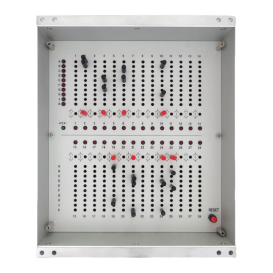
Page 14: Dimensions
14 Dimensions 14.1 Front view GHIELMETTI AG – 7UW50 - Technische Dokumentation ROR/09.02.2021 Page 14 of 19... -
Page 15: Back View
14.2 Back view GHIELMETTI AG – 7UW50 - Technische Dokumentation ROR/09.02.2021 Page 15 of 19... -
Page 16: Side View
14.3 Side view GHIELMETTI AG – 7UW50 - Technische Dokumentation ROR/09.02.2021 Page 16 of 19... -
Page 17: Specifications
-25 °C to +55 °C Storage temperature: Construction Mechanical dimensions: W/H/D = 219.4 x 267.4 x 177.3mm approx. 4.7 kg Weight: Connectors Clamp-connectors: max. wire diameter 2.5 mm² GHIELMETTI AG – 7UW50 - Technische Dokumentation ROR/09.02.2021 Page 17 of 19... -
Page 18: Ordering Data
EN 50081. Repair of the device is not recommended. If the device defect please send back to GHIELMETTI AG or contact us for support. 17.1 Replace the mini-fuse Select a replacement fuse 5 x 20 mm. Ensure that the rated value, time lag (medium slow) and code letters are correct. - Page 19 +41 32 671 13 13 (Phone) +49 3371 402 754 (Phone) +41 32 671 13 14 (Fax) +49 3371 610 548 (Fax) info@ghielmetti.ch deutschland@ghielmetti.ch www.ghielmetti.ch www.ghielmetti.ch GHIELMETTI offices GHIELMETTI AG – 7UW50 - Technische Dokumentation ROR/09.02.2021 Page 19 of 19...
Need help?
Do you have a question about the GKV 2x11x14 621 SS K and is the answer not in the manual?
Questions and answers