Table of Contents
Advertisement
Quick Links
Ailipu -
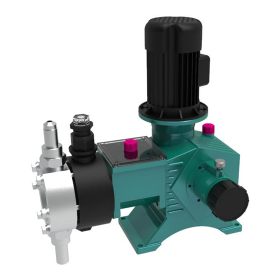
JYM1.6
Series Hydraulic Diaphragm Metering Pump
Operating Instruction
ZheJiang AILIPU Technology Co.,Ltd
Head Office:T1-9 Changhe Road, Binjiang District, Hangzhou
Production Base: No.2 Jinyuan Road, Binhai NewCity, Sanmen County, Taizhou, Zhejiang
Website: WWW.AILIPU.COM
Hotline: 400-728-1118
Version No.: ALP-190315-01/A
Advertisement
Table of Contents

Related Manuals for Zhejiang JYM1.6 Series

Summary of Contents for Zhejiang JYM1.6 Series
- Page 1 Ailipu - JYM1.6 Series Hydraulic Diaphragm Metering Pump Operating Instruction ZheJiang AILIPU Technology Co.,Ltd Head Office:T1-9 Changhe Road, Binjiang District, Hangzhou Production Base: No.2 Jinyuan Road, Binhai NewCity, Sanmen County, Taizhou, Zhejiang Website: WWW.AILIPU.COM Hotline: 400-728-1118 Version No.: ALP-190315-01/A...
-
Page 2: Table Of Contents
Contents I、Outline..............................3 1.1Production Code..........................4 II、Pump Structure and Working Principle....................4 2.1 Driving End..........................5 2.2 Hydraulic End..........................8 2.3 Pump flow regulation........................15 III、Installation............................16 IV、User Guide............................17 4.1 Preparation..........................17 4.2 Flow Adjustment (See above 2.3 Flow Adjustment)...............18 4.3 Operation..........................18 4.4 Flow Calibration........................18 4.5 hut Down the Pump.........................18 4.6 Oil filling into diaphragm chamber of hydraulic diaphragm metering pump...... - Page 3 Notes: If you encounter any problems when using the Ailipu metering pump, please first refer to the operation and maintenance manual for trouble removal. If the problem can’t be resolved, please contact your local Ailipu sales representative or our Technical Services Department.
- Page 4 Safe Operation Rules Cut off the power and relieve the pressure at the hydraulic end before repairing or moving the pump. When connecting or disconnecting the metering pump, make sure that the valve between the system pipe and the pump is closed. When inspecting the liquid end, if harmful or unknown liquid is measured at the liquid end, please wear appropriate protective equipment for operation, empty and clean the liquid end at the same time.
-
Page 5: I、Outline
I、Outline Zhejiang Ailipu Technology Co., Ltd. mainly researches, develops, produces and sells plunger metering pumps, mechanical diaphragm metering pumps, hydraulic diaphragm metering pumps and other special pumps. The technical parameters, testing rules, and others of our metering pumps are in strict accordance with GB7782-2008 Metering Pump andAPI std 675-2014 Positive Displacement Pumps-Controlled Volume. -
Page 6: Production Code
1.1Production Code Hydraulic Diaphragm Dosing Pump Production Code Head Type Diaphragm Rupture Alarm Rated Pressure Mpa Rated Capacity L/H YB - Standard Alarm S - 304 Articulated Joint Manual Welded Joint Series YC - Pressure Gauge 316L Hose Electric YD - Explosion Alarm Hydraulic Didphragm Type Hastelloy... -
Page 7: Driving End
2.1 Driving End The structure of metering pump driving end has 3 functions: First one is the retarding transmission; second one is conversion of dynamic form; third one is the adjustment of crank radius rotation. It’s a retarding mechanism constituted by worm and worm gears, and achieves dynamic retarding transmission. The crank-link mechanism constituted by eccentric wheel, connecting rod and crosshead hinge completes the transition from rotation to reciprocation. - Page 8 Figure 2 Structure Diagram of Driving End Table 1 List of parts Name Name Name Trademark Retaining ring cylinder head 136 Crossheaded screw M6x20 Seal ring Yx-d36 valve gasket F16-D Hole Circlips 62 Bracket gasket Valve ball F16-Q Hexagon countersunk head Adjusting handwheel valve seat F16-Z screwM6x10...
- Page 9 Column pressure Oil seal cover Valve sleeve F16-T O type sealing ring 9.5x1.8 Lock nut Pressure valve flangeF16-YL Stroke lock handle Column nut Outlet pipe F16-CG Adjusting screw Screw M12 Flange Adjusting seat Piston 36 Relief valve assemblyQAF1 External Circlips Bracket Bracket cover seal ring Deep groove ball bearing 6303...
-
Page 10: Hydraulic End
2.2 Hydraulic End 2.2.1 Structure The hydraulic end of the hydraulic diaphragm metering pump comprises medium chamber, diaphragm, hydraulic system and hydraulic oil tank, among which the medium chamber is composed of cylinder head, inlet and outlet valves, and inlet and outlet pipes and flanges, and the hydraulic system is composed of cylinder block, hydraulic cylinder, plunger, seal and “three-valve”... - Page 11 Hydraulic End Structure for 4 5 6 Double Diaphragm Dosing Pump 4 5 6 Figure 4 Hydraulic end structure for double diaphragm metering pump 2.2.2Working principal: Diaphragm separates the medium and hydraulic oil. The piston takes use of the power of crosshead in driving end to conduct reciprocating motion in hydraulic cylinder.
- Page 12 Diaphragm material and Diaphragm rupture alarm device Due to the medium which the pump conveys is flammable, explosive and corrosive, no leakage is allowed in the field, also, it requests the diaphragm used should be featured in corrosion resistance, strong pressure bearing capacity and long service life. So, adopt PTFE material as the diaphragm of the pump, it is characterized as excellent aging resistance, low hygroscopicity, outstanding self-lubricating performance, and corrosion resistance against almost all chemicals.
- Page 13 Figure 5 Diaphragm Rupture Warning Device Schematic Diagram 2.2.3“Three valves” of hydraulic system: The most outstanding feature of hydraulic diaphragm metering pump is the continuous process in which diaphragm separates medium and hydraulic oil, the plunger drives hydraulic oil, the oil drives diaphragm, and diaphragm absorbs and discharges media.
- Page 14 retaining ring is arranged at its left, and a tool withdrawal groove is located at the center of the valve spool, then a radial through-hole is drilled on the valve sleeve which is matched with the tool withdrawal groove. The limit valve is developed and designed into a reasonable and ingenious structure, the radial through-hole, tool withdrawal groove and spring are perfectly mounted, thus not only effectively controlling the diaphragm flexural deformation of the a limit spring at the rear dead point and automatically controlling the oil make-up...
- Page 15 2) Oil refilling valve A. Structure (see Figure 7) The oil refilling valve mainly comprises pressure valve nut, seal nut, valve seat, valve spool (connecting rod ball), spring, spring seat, filter and O-ring. The oil refilling mechanism is installed at the bottom of the cylinder block mounting position (see the structure diagram of pump hydraulic end), and the two O-rings on the valve must be intact for good sealing performance upon installation.
- Page 16 3) Deflation safety valve A. Structure (see Figure 8) J5AQF-01 Gasket GB893.1-86 Rtainer ring 65Mn Oil resistant GB3452.1-82 O ring rubber J5AQF-13 Valve core 40Cr J5AQF-12 65Mn Valve spring Oil resistant GB3452.1-82 O ring rubber J5AQF-11 spring 65Mn 陶瓷ceramic GB308-84 Valve ball Spring seat J5AQF-10...
-
Page 17: Pump Flow Regulation
B. Functional structure The deflation device mainly comprising deflation valve spool, deflation valve spring, valve ball, clearance adjustment pad and retaining ring is installed in the safety valve spool. Oil pressure fluctuates as the piston moves back and forth during operation. When the piston is pushed in, the deflation valve spool is jacked by spring;... -
Page 18: Installation
displacement of the crosshead and adjusting the flow. If the eccentricity between the E-type slide shaft and the center of the eccentric gear reaches half of the maximum stroke, the pump will reach the maximum stock (i.e., 100% of the relative stroke) and the maximum discharge flow. As the E-type slide shaft axially moves, the center of eccentric gear will get closer to the center of the slide shaft;... -
Page 19: User Guide
which has the function to prevent the pressure of the outlet pipe being too high, so as to protect the safe operation of the pump. The buffer tank is used to reduce the non-uniformity of the flow in the pipe and then to reduce the flow fluctuation. -
Page 20: Flow Adjustment (See Above 2.3 Flow Adjustment)
4.2 Flow Adjustment (See above 2.3 Flow Adjustment) 4.3 Operation Upon completion of the above preparatory work and confirmation, start the motor and put it into operation. The operation process should be stable, and there should be no abnormal noise, otherwise please shut down the pump to check. -
Page 21: Maintenance, Disassembly And Reassembly
Oil filling method: unscrew the entire exhaust safety valve assembly from the hydraulic cylinder block (without disassembling the parts) with wrench, fill transformer oil slowly into the diaphragm chamber through a small hole on the bottom plane for the safety valve mounting hole of the hydraulic cylinder block until oil overflows from the orifice, and then reassemble the exhaust safety valve assembly (check the O-ring on the bottom of safety valve for intactness before reassembly). -
Page 22: Disassembly And Reassembly
5.2 Disassembly and reassembly 5.2.1Disassembly of components for hydraulic end 1) Disconnect the inlet and outlet pipes from the pump, and remove the valve components, including pressure valve flange, inlet and outlet pipes (flanges), valve sleeve, valve ball and valve seat. 2) Screw off the set nut connecting the cylinder head to the cylinder block, and take out the diaphragm after removing the cylinder head. - Page 23 1) Before reassembling or replacing the worm and worm gear, measure and adjust the engagement center of the worm gear and the worm again until the center of worm is on the same central plane with the central plane of worm gear gorge circle as follows: apply a thin layer of red lead on the working surface of the worm gear, manually turn the worm gear for several times, observe its engagement point, and properly engage the worm with the worm gear by increasing or decreasing the seal paper pads on the bearing pedestal.
- Page 24 otherwise replacement is necessary. 5.2.5 Replacement, installation and commissioning of diaphragm 1) Disassemble the pump head (cylinder head) 2) Remove the old or damaged diaphragm and replace it with a new one. 3) Tighten cylinder pressure nuts in diagonal manner, able to make equal force of diaphragm. 4) Oil refill and test of diaphragm chambe, refers to IV :4.6 5.2.6 Cleaning of oil makeup valve 1) Unscrew the drain plug on the bottom of the hydraulic oil tank, and reassemble and tighten it after...
-
Page 25: Fault-Finding And Troubleshooting Checklist
VI、Fault-finding and Troubleshooting Checklist Fault Causes Troubleshooting 1. Power failure 2. One-phase or two-phase power 1. Check the power supply; failure; 2. Check whether the fuse and contactor contacts are in good 3. The thermal overload protection conditions; The motor cannot device is on;... - Page 26 unstable; 10. The suction level is too low. 1. The suction valve and discharge valve are damaged; 2. The piston ring is not tightly 1. Replace the valve; The pump sealed, and severely leaks; 2. Check or replace the piston ring and piston cylinder; pressure does not 3.
- Page 27 valve; 4. It is unnecessary to replace parts if no damage occurs; 4. The fit clearance between the 5. Check and clean the safety valve, and adjust its opening worm gear and the worm is too pressure. large; 5. A sound is heard when the pipeline safety valve is opened.
-
Page 28: After Sales Service
VII、After Sales Service If you encounter any problems during use, please dial our after-sales service phone number (each metering pump has a unique factory number on the nameplate, please inform us of this number when contacting our after-sales service personnel, so that we can verify the corresponding model and technical parameters of the product.) Our after-sales service phone number: 0086-576-8337185... - Page 29 All rights reserved. Plagiarism is not allowed. No.2 Jinyuan Road, Binhai NewCity, Sanmen County, Taizhou, Zhejiang Add: Tel:0576-83351188 83351225 Fax:0576-83351093 83351522 E-mail:alp@ailipu.com Post code:317100 http://www.ailipu.com The company reserves the right of final interpretation...
Need help?
Do you have a question about the JYM1.6 Series and is the answer not in the manual?
Questions and answers