Advertisement
Quick Links
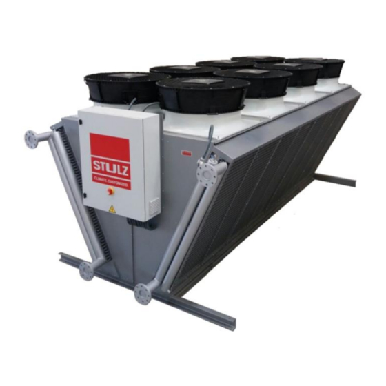
AXIAL DRY-COOLERS SERIES EV/EVI
1.
MANUFACTURER'S DATA
STULZ TECNIVEL, S.L. St. Ponferrada 30 - 28947- Fuenlabrada -
Corporate Name
Adress
Contact information
Telephone
E-mail
2. INTRODUCTION
By means of this document, is intended to synthesize all the necessary information to install, use
and maintain in perfect conditions
the
axial
STULZ TECNIVEL, S.L.
The
axial
dry-coolers
are equipment that are part of an installation and is forbidden the
commissioning of the unit until the whole installation fulfills with all applicable regulations and
directives.
3. TRANSPORTATION AND INSTALLATION INSTRUCTIONS
3.1 TRANSPORTATION
Note: Do not drag the unit. For its displacement, it is lifted with devices provided for this purpose.
3.2 ANCHORAGE
All models provide anchor holes
Ø14
mm, so they will be used for the attachment.
Units include fans that are static and dynamic balance so is no needed an extra isolation.
It is important that the dry-coolers once installed are perfectly level, so it is recommended to use a
system that corrects the level deviations that may exist. In any case it is recommended to place a
rubber mat to absorb vibrations.
3.3 CONNECTION TO THE HIDRAULIC SUPPLY
Connect the unit to the hydraulic water supply, respecting the diameters of the connections of the
installation, so as to avoid possible pressure drops that reduce the performance of the same. The
standard design is made with countercurrent flows between water and air. Therefore, the entry must
be made by A and the exit by B. See the following figure.
Madrid - ESPAÑA
St. Carabaña 25C - 28295 - Alcorcón - Madrid -
ESPAÑA
+34 91 517 83 20
stulztecnivel@stulztecnivel.com
dry-coolers
of the EV and EVI
series,
manufactured by
B
Note: STULZ TECNIVEL, S.L. is not responsible for any damage that may be caused by the
freezing of water inside the heat exchanger. This can be caused by the non-application of (glycol)
antifreeze fluid in the proper proportions or any other system that guarantees the non-freezing of the
water contained in the circuit.
Neither is responsible for the use of fluids other than those provided. It is particularly important to
take this recommendation into account at the time of performing the hydraulic tests prior to
commissioning.
3.4 CONNECTION TO THE ELECTRIC SUPPLY.
Make sure that the voltage and frequency of the power supply network matches that indicated on
the rating plate.
For those units that are not delivered connected: Remove the cover of the motor terminal box and
connect directly to the terminals, also connecting the
protector that will be inserted in the control circuit from the motor coil of the contactor. Tighten the
terminal screws and pull lightly on the plugged cables to ensure that they are firmly secured, and
replace the motor terminal box cover.
4. INSTRUCTIONS FOR THE COMMISSIONING
Once the installation has been done and its cleaned, verify that there are no leaks in the fluid circuit
and the water charge ,it should be checked that the fans rotate in the correct direction, aspirating
from the coils (or driving through it in case of going on impulsion). Otherwise permute two phases,
then the unit will be ready to operate.
5. MAINTENANCE INSTRUCTIONS
The motors incorporate bearings with permanent lubrication, so the maintenance will be reduced to
the cleaning of the coils and fan blades, which will be carried out with a frequency that can change
with the fouling rate.
For cleaning, can be use pressurized air or water with detergent then rinsing with clean water. The
direction of the jet (air or water) must be parallel to the air flow. Leaning the jet can damage the
exchanger fins.
In case a coil result damaged, this could be substituted by one for replacement. For this operation, it
is recommended to proceed in an area with the available space that allows it removal. In case the
equipment is part of a system it is recommended it separation from it, for it later handling. For it
substitution, it will be needed to dismantle the coil frame panel, the coil will be hold by chains or
other auxiliary element, then remove the fixing screws that join the coil to the structure. Afterward
remove one of the frontal panels, to access to the interior of the unit so as to remove the internal
fixation.
B
A
grounding wire
the terminals of the thermal
Advertisement

Related Manuals for Stulz Tecnivel EV

Summary of Contents for Stulz Tecnivel EV
- Page 1 EV and EVI series, manufactured by Note: STULZ TECNIVEL, S.L. is not responsible for any damage that may be caused by the STULZ TECNIVEL, S.L. freezing of water inside the heat exchanger. This can be caused by the non-application of (glycol)
- Page 2 6. NORMAL CONDITIONS OF USE AND LIMITS 7. RISK SITUATIONS 8. ELIMINATION OR REDUCTION OF RISK 9. RESIDUAL RISK Rev 00.0 26/04/2018 This document is property of STULZ TECNIVEL, S.L., not being allowed its total or partial reproduction without a prior express consent.
Need help?
Do you have a question about the EV and is the answer not in the manual?
Questions and answers