Harman Kardon AVR 144 Owner's Manual
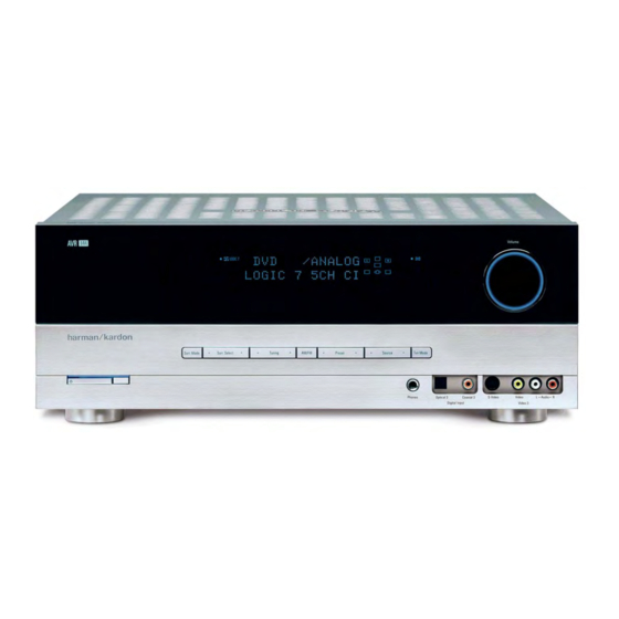
5.1-channel audio/video receiver
Hide thumbs
Also See for AVR 144:
- Settings manual (3 pages) ,
- Quick start manual (2 pages) ,
- Product view (1 page)
Table of Contents
Advertisement
Advertisement
Table of Contents

Related Manuals for Harman Kardon AVR 144


Summary of Contents for Harman Kardon AVR 144
- Page 1 ® Designed to Entertain. AVR 144 AUDIO/VIDEO RECEIVER OWNER’S MANUAL...
-
Page 2: Safety Information
CAUTION RISK OF ELECTRIC SHOCK SAFETY INFORMATION DO NOT OPEN 1. Read Instructions. All the safety and operating instruc- tions should be read before the product is operated. 2. Retain Instructions. The safety and operating instruc- tions should be retained for future reference. 3. -
Page 3: Important Safety Information
• Do not obstruct the ventilation slots on the top of the unit, or place objects directly over them. • Due to the weight of the AVR 144 and the heat generated by the amplifiers, there is the remote possibility that the rubber padding on the bottom of the SAFETY INFORMATION unit’s feet may leave marks on certain wood or veneer materials. -
Page 5: Table Of Contents
Step Six – Plug in AC Power Step Seven – Insert Batteries in Remote Step Eight – Program Sources Into the Remote Step Nine – Turn On the AVR 144 INITIAL SETUP Using the On-Screen Menu System Step One – Determine Speaker Size Step Two –... -
Page 6: Introduction
In the years since our first single-channel component was introduced, Harman Kardon has offered a number of receiver models, each an improvement upon its predecessors, leading to the AVR 144, a 5. 1 -channel digital audio/video receiver that offers a wealth of listening and viewing options, all in an affordable elegant package. -
Page 7: Audio Inputs
• Programmable seven-device main remote control • Source input renaming • A/V Sync Delay Supplied Accessories The following accessory items are supplied with the AVR 144. If any of these items are missing, please contact Harman Kardon customer service at www.harmankardon.com. • System remote control •... -
Page 8: Front-Panel Controls
FRONT-PANEL CONTROLS Main Power Switch: This is a mechanical switch that turns the power supply on or off. It is usually left pressed in (On position) at all times, and cannot be turned on using the remote control. Standby/On Switch: This is an electrical switch that turns the receiver on for playback, or leaves it in standby mode for quick turn-on using this switch or the remote control. -
Page 10: Rear-Panel Connections
REAR-PANEL CONNECTIONS AM and FM Antenna Terminals: Connect the included AM and FM antennas to their respective terminals for radio reception. Front, Center and Surround Speaker Outputs: Use two- conductor speaker wire to connect each set of terminals to the correct speaker. -
Page 12: Remote Control Functions
Power On Button: Press this button to turn on the AVR or another device. The Master Power Switch on the AVR 144’s front panel must first have been switched on. Mute Button: Press this button to mute the AVR 144’s speaker and headphone outputs temporarily. - Page 13 IR Transmitter Lens Power On Program Indicator AVR Selector AM/FM Test Tone Sleep DSP Surround On-Screen Display Channel Level Digital Input Tuning Mode Direct Station Entry Tuning Tone Mode Night Mode Track Skip Transport Controls Mute Power Off Input Selectors 6-Channel Input Selector TV/Video Volume Control...
- Page 14 REMOTE CONTROL FUNCTIONS This is done using the on-screen menu system, as described in the Initial Setup section. Numeric Keys: Use these buttons to enter radio station frequencies when using the tuner (after pressing the Direct Button), or to select station presets.
-
Page 15: Introduction To Home Theater
Surround sound helps to immerse you in the musical or film presentation for increased realism. The AVR 144 may have up to five speakers connected directly to it (plus a subwoofer). Each speaker is powered by its own amplifier chan- nel inside the receiver. -
Page 16: Connections
Figure 3 – Subwoofer Connecting Source Devices to the AVR The AVR 144 is designed to process audio and video input signals, playing back the audio and displaying the video on a television or moni- tor connected to the AVR. These signals originate in what are known as “source devices,”... -
Page 17: Audio Connections
Audio Connections There are two formats for audio connections: digital and analog. Digital audio signals are of higher quality, and are required for listening to sources encoded with digital surround modes, such as Dolby Digital and DTS. There are two types of digital audio connections commonly used: coaxial and optical. -
Page 18: Antennas
S-video and then composite video. Antennas The AVR 144 uses separate terminals for the included FM and AM antennas that provide proper reception for the tuner. The FM antenna uses a 75-ohm F-connector. See Figure 11. -
Page 19: Speaker Placement
Before you begin to connect cables, it is important to set up your speakers in their correct locations in the room. Optimally, the speakers should be placed in a circle with the listening position at its center. The distance from the listening position to the video display forms the radius of the circle. -
Page 20: Installation
Figure 14 – Speaker Connections Step Two – Connect the Subwoofer Connect the Subwoofer Output on the AVR 144 to the line-level input on your subwoofer. See Figure 15. Consult the manufacturer’s guide for the subwoofer for addition7.2(Sn2re a locre 14.)]TJ6.6552 0 0 6.6552 88131 c968.4166 (See Figu –)-480.4( the Subwoaker Connenish.)]TJ/F3 1 Tf11.6467 0 0 11.3... - Page 21 DVD source. When you select “DVD” as your source using the front panel or the remote, the correct connections for your DVD player will be used. Device Type AVR 144 Source Input VCR, DVR, PVR, Video 1 TiVo or other...
- Page 22 Keep this in mind as you connect other source devices that you may wish to make recordings from. 2. The AVR 144 does not have any digital audio outputs. If you wish to make recordings, your source must be connected to any of the AVR 144’s analog audio inputs, and your recorder...
-
Page 23: Step Five - Connect Video Display
AVR 144. Make sure your source is connected to any of the AVR 144’s analog audio inputs, and connect your recorder to either the Video 1 or Tape Analog Audio Outputs. The AVR 144 will not convert a digital audio input signal to analog. -
Page 24: Step Eight - Program Sources Into The Remote
Input Selector buttons to access the codes for the devices programmed into the remote. At the factory, the AVR 144’s codes and the codes to control many Harman Kardon DVD and CD players are preprogrammed. If you have other source devices in your system, follow these steps to program the correct codes into the remote. -
Page 25: Step Nine - Turn On The Avr 144
Master Power Switch in the ON position, even when the receiver is not being used. Figure 28 – Power Switches 2. There are several ways in which the AVR 144 may be turned on from Standby mode. a) Press the Standby/On Switch on the front panel. See Figure 28. -
Page 26: Initial Setup
INITIAL SETUP Before you begin enjoying your new receiver, a few adjustments should be made to configure the AVR 144 to match your actual system. Make sure that you have connected a video display to either the S- video or composite video monitor output on the receiver. When you turn on your display and the AVR, you should see a blue screen. -
Page 27: Step Two - Measure Speaker Distances
25Hz – 150Hz. In this case, the higher number is most important and should be noted in the worksheet. The purpose of programming this information into the AVR 144 is to program the receiver’s bass management, which determines which speakers the receiver will use to play back the low-frequency (bass) portion of the source program. -
Page 28: Speaker Crossover Menu
INITIAL SETUP LEFT/RIGHT: This line tells the AVR 144 the capabilities of your front left and right speakers. Use the ‹/› Buttons to select either SMALL or LARGE for these speakers. CENTER: Move the cursor to the line for the center speaker, and use the ‹/›... -
Page 29: Delay Adjust Menu
The LFE line sets the frequency for a low-pass filter that determines what information is sent to the subwoofer for playback. Since the sub- woofer output combines low-frequency information for all channels, in order to make sure that no information is lost due to different speakers having different capabilities, the subwoofer filter should be matched to the highest crossover frequency used for any speaker group. -
Page 30: Step Five - Configure Sources
⁄ ¤ If you would like to set your levels using the AVR 144’s internal test tone, you will need to adjust the TEST TONE SEQ and TEST TONE lines as follows. TEST TONE SEQ: When this setting reads AUTO, the test tone will auto-... - Page 31 AUTO POLL: The Auto Poll feature is used when both an analog audio and digital audio connection have been made for one source device. If for some reason no digital signal is available, the AVR 144 will switch to the analog inputs for the source. This situation can occur with some cable or satellite television broadcasts, where some channels are broad- cast with digital audio and others with analog audio.
-
Page 32: Operation
See Figure 41. Figure 41 – Power Switches There are several ways in which the AVR 144 may be turned on: a) Press the Standby/On Switch on the front panel. See Figure 41. -
Page 33: Mute Function
Input Selector on the remote (see Figure 43). Figure 49 – Source Select and Tuner Band Buttons The AVR 144 will switch to the audio and video inputs assigned to that source. If you set the BASS MGR setting in the Speaker X-Over menu to INDEPENDENT, the AVR 144 will change the speaker size configura- tion to the one you programmed for the source. -
Page 34: Audio Input Selection
If the Auto Poll feature has been left ON in the Input Setup menu, and if a digital audio input has been assigned to the source, the AVR 144 will first check the digital audio input for a signal. If a signal is present, the AVR 144 will select the digital audio input. -
Page 35: Using The Tuner
Manual Setup menu. Consult the owner’s guide for your multi- channel player for more information. Using the Tuner The AVR 144’s built-in tuner may be selected in one of three ways (see Figure 53): 1. Press the Source Selector Button on the front panel repeatedly until the tuner is selected. -
Page 36: Selecting A Surround Mode
Surround mode selection can be as simple or sophisticated as your individual system and tastes. Feel free to experiment with the many available surround modes on the AVR 144, and you may find a few that become your favorites for certain sources or program types. Although... -
Page 37: Advanced Functions
Much of the AVR 144’s performance is handled automatically, with little intervention required on your part. However, the AVR 144 is a sophisti- cated component, and is capable of being customized to suit your par- ticular system and your tastes. In this section we describe some of the more advanced adjustments available on the AVR 144. -
Page 38: Surround Modes
There is no harm in experimenting with all of the modes available with any given source material. Table 4 offers a brief description of each mode the AVR 144 is capable of using, and also indicates the types of incoming signals or digital bitstreams the mode may be used with. -
Page 39: Dolby Surround Settings
MODE setting in the System Setup menu has been changed to OFF. You may observe that other surround modes are available for use with the multi- channel digital bitstreams. If you would prefer the AVR 144 to use one of those alternate modes any time the same digital signal is detected, then select that mode while the multichannel bitstream is present, and then change the DEFAULT SURR MODE setting in the System Setup menu to OFF. - Page 40 ADVANCED FUNCTIONS Surround Mode Description Dolby Pro Logic II Analog decoder that derives five full-range, discrete main audio channels from matrix surround-encoded or 2-channel analog sources. Four variants are available. Dolby Pro Logic II Variant of Dolby Pro Logic II that is optimized for movie and Movie television programs.
- Page 41 Cinema matrix encoding, Logic 7 Cinema mode increases center channel intelligibility. Logic 7 The AVR 144 is programmed at the factory to default to this mode for Music 2-channel signals. Logic 7 Music mode is well suited to conventional 2-channel music recordings.
-
Page 42: System Settings
Advanced Remote Control Functions The AVR 144 remote control not only operates the AVR 144, but it also serves as a universal remote that may be programmed to operate many of your other home theater components, as described in the Installation section. -
Page 43: Punch-Through Programming
Processor Reset If you wish to fully reset the AVR 144 to its factory defaults, or if it behaves erratically after a power surge, first turn the Master Power Switch off and unplug the AC Power Cord for at least three minutes. -
Page 44: Troubleshooting Guide
In addition to the items shown above, additional information on troubleshooting possible problems with your AVR 144, or installation-related issues, may be found in the list of "Frequently Asked Questions" which is located in the Product Support section of our Web site at www.harmankardon.com. -
Page 45: Technical Specifications
AVR 144 TECHNICAL SPECIFICATIONS Audio Section Stereo Mode Continuous Average Power (FTC) 40 Watts per channel, 20Hz–20kHz, @ <0.07% THD, both channels driven into 8 ohms Five-Channel Surround Modes Power per Individual Channel Front L&R channels: 30 Watts per channel @ <0.07% THD, 20Hz–20kHz into 8 ohms... -
Page 46: Appendix
APPENDIX Appendix – Default Settings, Worksheets, Remote Product Codes Table A1 – Source Input Setting Defaults Source Video 1 Title Component Comp V 1 Comp V 2 Video Input Audio Input Coax 1 Analog Auto Poll Surround Logic 7 Logic 7 Mode* 5CH Music 5CH Music... - Page 47 Table A4 – Source Input Settings Source Title Video Input Component Video Input Audio Input Auto Poll Surround Mode Table A5 – Speaker/Channel Settings Source Bass Manager: Global/Independent Left/Right Speaker Size Center Speaker Size Surround Speaker Size Subwoofer Left/Right Speaker Crossover Center Speaker Crossover Surround Speaker Crossover Subwoofer Crossover...
- Page 48 APPENDIX Table A6 – Remote Control Codes Source Input Product Type (circle one) Video 1 VCR, PVR Video 2 Cable, Satellite Video 3 CD, CDR Tape Cassette Table A7 – System Settings Feature Default Setting VFD Fade Time-Out Volume Default Default Vol Set –25dB Semi-OSD Time-Out...
- Page 49 Refer to the numbered buttons in Figure 63 when using the Function List. Figure 63 – Remote Control Function List Reference APPENDIX 26 27 32 33 36 37 40 41 43 44 45 46 47 48 49 50 51 52 53 63 64 66 67 68...
- Page 50 APPENDIX Table A8 – Remote Control Function List Button Name AVR Function Power On Power On Power On Power Off Power Off Power Off Mute Mute Mute AVR Select AVR Select DVD Input Select DVD Select CD Input Select CD Select Tape Tape Input Select Tape Select...
- Page 51 Button Name AVR Function Direct Direct Tuner Entry Angle Clear Clear Clear Preset Up Preset Tune Up Slow Forward Tuning Down Tuning Down Prev Chapter Tone Tone mode D. Skip Disc Skip (DVD) Disc Skip Preset Down Preset Tune Down Slow Rev Macro 1 Macro 1...
- Page 52 APPENDIX Refer to Tables A9 through A15 when programming the codes for your components into the remote. Table A9 – Remote Control Product Codes – TV Manufacturer/Brand Setup Code Number AIWA A MARK ADMIRAL AKAI AMPRO ANAM BLAUPUNKT BROKSONIC CANDLE CAPEHART CENTURION CENTRONIC...
- Page 53 Manufacturer/Brand Setup Code Number LOGIK LUXMAN MAGNAVOX MARANTZ MATSUI MEMOREX METZ MINERVA MITSUBISHI NATIONAL NIKEI ONKING ONWA OPTONICA ORION PANASONIC PHILCO PHILIPS PIONEER PORTLAND PROSCAN PROTON QUASAR RADIO SHACK REALISTIC RUNCO SAMPO SAMSUNG SANYO SCOTT SEARS SHARP SIEMENS SIGNATURE SONY SOUNDESIGN SPECTRICON SYLVANIA...
- Page 54 APPENDIX Manufacturer/Brand Setup Code Number TEKNIKA TELERENT TERA THOMSON TOSHIBA TOTEVISION VIDEO CONCEPTS VIDTECH WARDS YAMAHA YORK YUPITERU ZENITH ZONDA...
- Page 55 Table A10 – Remote Control Product Codes – VCR Manufacturer/Brand Setup Code Number AIWA AKAI 048 108 109 126 AMPRO AUDIO DYNAMICS 018 048 BROKSONIC 110 147 CANDLE 134 135 CANON 135 140 CAPEHART CITIZEN CRAIG 045 116 DAEWOO 017 094 104 DAYTRON 018 048 DYNATECH...
- Page 56 APPENDIX Manufacturer/Brand Setup Code Number REALISTIC 017 020 040 045 159 SALORA SAMSUNG 045 095 105 109 SANSUI 048 116 147 SANYO 017 020 SCOTT 110 112 SEARS 017 020 SHARP 129 156 SONY 080 129 SOUNDESIGN SYLVANIA SYMPHONIC TANDY 017 040 TASHICO TATUNG...
- Page 57 Table A11 – Remote Control Product Codes – CD Manufacturer/Brand Setup Code Number ADCOM AIWA AKAI AUDIO TECHNICA AUDIOACCESS AUDIOFILE CALIFORNIA AUDIO CAPETRONIC CARRERA CARVER CASIO CLARINETTE DENON EMERSON FISHER FRABA FUNAI GENEXXA GOLDSTAR/LG HAITAI HARMAN KARDON HITACHI INKEL JC PENNEY JENSEN KENWOOD LOTTE...
- Page 58 APPENDIX Manufacturer/Brand Setup Code Number REALISTIC SANSUI SANYO SCOTT SHARP SHERWOOD SONY SOUNDSTREAM SYMPHONIC TAEKWANG TEAC THETA DIGITAL TOSHIBA VECTOR RESEARCH VICTOR WARDS YAMAHA YORK Table A12 – Remote Control Product Codes – DVD Manufacturer/Brand Setup Code Number APEX DIGITAL DENON 019 051 003 004...
- Page 59 Table A13 – Remote Control Product Codes – SAT Manufacturer/Brand Setup Code Number ALPHASTAR ALPHASTAR DBS ALPHASTAR DSR BIRDVIEW CHANNEL MASTER 320 321 CHAPARRAL 315 316 CITOH DRAKE 313 317 DX ANTENNA 331 352 ECHOSTAR 395 397 ELECTRO HOME FUJITSU 324 329 GENERAL INSTRUMENT 303 311...
- Page 60 APPENDIX Table A14 – Remote Control Product Codes – TAPE Manufacturer/Brand Setup Code Number HARMAN KARDON Table A15 – Remote Control Product Codes – CBL Manufacturer/Brand Setup Code Number 001 011 ALLEGRO AMERICAST ARCHER BELCOR CABLE STAR CITIZEN COLOUR VOICE 085 090 DIGI EAGLE...
- Page 61 Manufacturer/Brand Setup Code Number REMBRANT SAMSUNG 003 072 186 SCIENTIFIC ATLANTA 183 203 221 222 SEAM SIGNATURE 001 188 SPRUCER 053 177 189 STARCOM 002 011 163 STARGATE TANDY TELECAPATION TEXSCAN TIMELESS TOCOM 170 205 UNITED CABLE UNIVERSAL 039 042 113 VIDEOWAY 124 211 VIEWSTAR...
- Page 62 NOTES...
- Page 63 NOTES...
- Page 64 ® 250 Crossways Park Drive, Woodbury, New York 11797 www.harmankardon.com © 2006 Harman International Industries, Incorporated. All rights reserved. Part No. CQX1A1153Z...
Need help?
Do you have a question about the AVR 144 and is the answer not in the manual?
Questions and answers