
Summary of Contents for Allied MultiPrep System 15-2000-GI
- Page 1 ™ ™ 115 V AC & 230 V AC & CE Operation Manual 2376 E. Pacifica Place, Rancho Dominguez, CA 90220 * 310-635-2466 www.alliedhightech.com 03/13, Version 7.6...
-
Page 2: Table Of Contents
Table of Contents Safety Precaution Sheet MultiPrep™ System Technical Data Warranty/Service Installation Electrical Plumbing MultiPrep™ Base Operation 9-12 Faceplate Diagram Electronics Calibration Platens, Splash Ring Button Functions 10-11 Theory of Operation, MultiPrep™ System MultiPrep™ Head Installation MultiPrep™ Head Operation 13-18 Vertical Movement &... -
Page 3: Safety Precaution Sheet
Safety Precaution Sheet Warning! Please read carefully before operating the machine: The operator(s) must be properly trained in all operation aspects of this machine according to this manual. The machine must be placed on a safe, suitable surface to allow for operation without hindrance to the controls. -
Page 4: Multiprep™ System Technical Data
MultiPrep™ System Technical Data Model: MultiPrep™ System Item Number: #15-2000-GI, #15-2000-GI-230 Description: Precision Polishing System Serial Numbers: ______________________MultiPrep™ head ______________________MultiPrep™ base Voltage: 115 V AC_________ 230 V AC_________ (check one) Frequency: Factory calibrated to 60 Hz (operates at 50 Hz or 60 Hz) Motor: ¼... -
Page 5: Warranty/Service
Allied, are often the quickest and easiest way to return a product to active service. If you wish to return a product to Allied for warranty repair, you must first obtain a Return Equipment Authorization number (REA). An REA may be obtained from your Product Application Specialist, or from a member of our Technical Services staff. - Page 6 Non-warranty repairs are made with the same attention to detail and commitment to quality workmanship that is provided to “in” warranty customers. Thank you for choosing Allied, and please let us know if you have comments or questions about these warranty provisions.
-
Page 7: Installation
Installation The unit should be placed on a clean, dry surface with the control panel facing the front of the counter/table on which it will be placed. Electrical Before installing the plumbing, all electrical functions should be tested. See page 9 for a diagram of the control panel and pages 10-11 for illustrations of the buttons and their respective functions. -
Page 8: Plumbing
Plumbing Flow Rate: ½ gallons per minute (1.9 L/minute) Minimum Inlet Water Pressure: 25 psi (1.76 kgf/cm²) Maximum Inlet Water Pressure: 50 psi (3.52 kgf/cm²) Drainage: 1 gal/minute (3.8 L/minute) (recommended @ 30 psi) Inlet Tubing: ¼" OD (6.35 mm) Drainage Tubing: 1¼"... -
Page 9: Multiprep™ Base Operation
AC receptacle for at least five (5) seconds, and then back on for normal operation. During the electronics calibration procedure, only the main power switch can stop the machine. Please contact Allied if there are any questions or concerns regarding this process. -
Page 10: Platens, Splash Ring
Platens The 8" aluminum platen included with the machine is precision lapped and hard anodized. The lapping ensures flatness, and the anodizing hardens the aluminum, making it durable and resistant to scratches and dings. On the underside a center hole is used to help locate the platen on center with the platen base. -
Page 11: Theory Of Operation, Multiprep™ System
Coolant The COOLANT button activates and deactivates the water solenoid. When a water supply line is installed, the solenoid allows water to pass through when activated. Keypad The keypad is used for platen RPM selection, timer entry and speed selection for the oscillator and rotation functions of the MultiPrep™... -
Page 12: Multiprep™ Head Installation
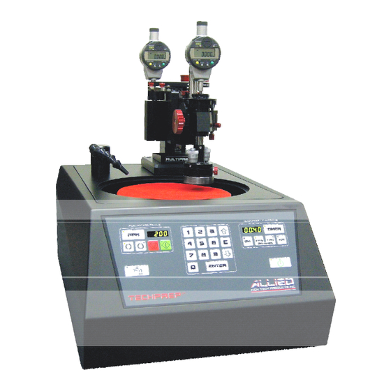
Theory of Operation, MultiPrep™ System The MultiPrep™ head is a high-precision sample preparation instrument that provides quantifiable material removal and geometric/angular control for the most demanding preparation applications. A suspension arm supports a free-floating spindle to which the sample is secured using a fixture. The vertical position of the suspension arm relative to the platen or abrasive plane is controlled using the vertical adjustment knob, allowing versatile and flexible positioning options to accommodate various sized samples and fixtures. -
Page 13: Multiprep™ Head Operation
The leveling plate is mounted to the MultiPrep™ base with three (3) stainless steel socket head cap screws. These screws are used to align the rotation spindle of the MultiPrep™ head perpendicular to the platen surface of the MultiPrep™ base (page 21). After the MultiPrep™... -
Page 14: Fixture Attachment
Fixture Attachment All fixtures are mounted to the bottom plate of the micro-hub assembly at the bottom of the spindle. Each fixture has a common U-shaped cutout. The flat edge of the fixture is positioned against the reference edge located behind the cam-lock plunger (Figure 8). Note: The spindle should be raised using the vertical adjustment knob so the sample and fixture fit without contacting the platen/abrasive. -
Page 15: Rotation
Rotation 1. Full Rotation: Sample rotation is activated by pressing the FULL button in the “MultiPrep™ Controls” box on the control panel. The rotation speed is variable, with eight (8) settings. The speed number is arbitrary, increasing from 1 to 8. To program the speed, press the FULL key once, then press it again and hold it until the LED turns orange and a double beep is heard. -
Page 16: Oscillation
Oscillation 1. Range: To set the sweep range, loosen the range thumbscrew on the oscillator pulley (Figure 10). Slide the dovetail bar so the drive pin moves closer to or farther from the center of the hub. Moving the pin closer to the center will provide a smaller sweep (range), and moving it farther from the center will create a larger sweep. -
Page 17: Angular Adjustments
Angular Adjustments Angular adjustments are necessary for certain polishing procedures, or for correcting any misalignment of a sample to the fixture, due to fluctuations in glue, wax, or other sample mounting media. The adjustments are made by rotating either of the micrometers located on the micro-hub. Both micrometers are oriented 90º... -
Page 18: Sample Load
For additional assistance in aligning the MultiPrep™ System, a video CD has been included with each machine. This CD contains an AVI file that can be played on most computers with DivX-compatible video player software. Please contact Allied for more information. -
Page 19: Step 1: Verification Of Platen Run-Out
MultiPrep™ System Alignment – Instructions Step 1: Verification of Platen Run-out With the first step of the alignment procedure, it is important to make sure that the total vertical run-out (movement up and down as it rotates) of the platen is within 4 µm. - Page 20 If the run-out is still more than 5 µm after cleaning, see the Maintenance section on pages 35-36, or contact Allied for further service options. Note: The platen and platen base are precision lapped surfaces; however, the tolerances may vary up to 2-3 µm each. The platen orientation, as it rests on the platen base, can affect the overall (compounded) run-out.
-
Page 21: Step 2: Perpendicular Alignment Of Spindle To Platen
Step 2: Perpendicular Alignment of Spindle (sample rotation axis) to Platen Vertical spindle alignment is necessary to establish perpendicularity of the rotation axis to the platen. This ensures the sample will remain in contact with the platen during an entire rotation cycle. Alignment of the axis prevents coning of the sample and keeps it parallel to the platen. -
Page 22: Step 3: Alignment Of Micro-Hub Assembly To Platen
5) If at the 9 o’clock position the needle has rotated clockwise, tighten the screw at the right rear corner of the leveling plate until the needle returns to “100”. If it has rotated counterclockwise, loosen the screw at the right rear corner of the leveling plate until the needle returns to “100.”... - Page 23 Procedure: 1) If proceeding from the previous section, remove the adapter plate and indicator and separate the two components so the indicator can be used by itself. 2) Manually position the indicator tip to about a 25º forward angle, and secure the indicator to the platen using double sided adhesive tape so the indicator tip is facing the micro- hub assembly.
-
Page 24: Explanation Of Digital Indicators
Explanation of Digital Indicators Button Functions The functions of the 3 buttons on each digital indicator (Figure 27) are as follows: Button 1: Push and release to switch between inches and millimeters. Button 2: Push and release to zero the display OR push and hold for more than 2 seconds to enter ABS mode, where preset values can be set for the indicator. -
Page 25: Specific Material Removal
Because sound is used as an indicator of contact, this method has limitations to its precision and is therefore recommended for coarse grinding applications. The rear digital indicator spindle can move up or down within a range of about 2½", while the MultiPrep™... - Page 26 Fine Material Removal (<100 µm) For fine material removal (<100 µm), the front digital indicator should be used, along with diamond lapping films 3 µm and finer, on samples having surface areas less than 25 mm 1. Place the desired abrasive onto the platen. 2.
-
Page 27: Fixture Descriptions
Fixture Descriptions #15-1005, Cam-Lock Adapter This adapter is used with fixtures #15-1010 and #15-1013 to allow easier attachment to the micro-hub assembly. It also positions the fixtures so the sample makes contact nearest to the center of the platen; this allows for maximum abrasive usage. #15-1010 &... - Page 28 #15-1018, SIMS Pyrex® Fixture This fixture features a ½" round Pyrex® glass insert secured to an aluminum body. It allows light to pass through the Pyrex® for transmitted light observation of sample thickness, which is useful when thinning silicon based devices from the backside for SIMS analysis. Samples are secured to a square glass microscope slide using EpoxyBond 110™...
- Page 29 #15-1045/46/47/48, Multipurpose Fixtures Each of these fixtures is designed to mechanically secure samples that cannot be waxed or secured well enough to the Cross-Sectioning Paddle (#15-1010). Fixtures #15-1046/48 orient microelectronic packages and devices diagonally (45 degrees) to the platen. Fixtures #15-1045/47 provide sample orientation parallel to the platen.
-
Page 30: Options/Accessories
Options/Accessories Label Item # Description 15-1005 Cam-Lock Adapter (to secure 15-1010 & 15-1013 to the micro-hub) 15-1010 Cross-Sectioning Paddle 15-1010-RE Cross-Sectioning Paddle, with Reference Edge 15-1013 TEM Wedge/FIB Thinning Paddle with Pyrex® (5 mm x 3.5 mm) 15-1018 SIMS/Backside Pyrex® Fixture 15-1020 Parallel Polishing Fixture, 2.25"... -
Page 31: Maintenance
Maintenance Platen Base Cleaning and Platen Cleaning/Storage Vertical run-out of the platen must be kept at a minimum in order to optimize the precision of the MultiPrep™ System. To prevent oxidation from water and polishing suspensions on the platen base, it is very important to clean and dry this surface after each use of the machine. Warm, soapy water or a mild solvent is recommended. - Page 32 It MUST be cleaned frequently to avoid overflowing of the bowl. Damage to electrical and mechanical components as a result of overflow is not covered under the warranty. Spare Parts Contact Allied for a list of recommended spare parts.
-
Page 33: Troubleshooting
Troubleshooting Problem Cause Solution Use a mounting material with better The edge was not properly adhesion. supported, because there was a gap between the mounting Degrease and clean the sample material and the sample. thoroughly before mounting. Edge Rounding The polishing cloth was too soft Use a more rigid polishing cloth. - Page 34 The polishing motion was in one Rotate the sample to create a random direction only. polishing pattern. Comet Tails The power head and platen Set the power head and platen to rotate speeds were too different, which at similar speeds. created an unidirectional effect The polishing cloth was too rigid Use a softer polishing cloth.
-
Page 35: Wiring Diagrams
MultiPrep™ System Wiring Diagrams... -
Page 39: Ce Certificates (230 V Ac Multiprep™ Systems Only)
CE Certificates... - Page 42 (This page has been left blank intentionally)
- Page 43 (This page has been left blank intentionally)
- Page 44 2376 East Pacifica Place, Rancho Dominguez, CA 90220 (800) 675-1118 (US & Canada) * (310) 635-2466 (Worldwide) * (310) 762-6808 (Fax) www.alliedhightech.com...
Need help?
Do you have a question about the MultiPrep System 15-2000-GI and is the answer not in the manual?
Questions and answers