Table of Contents
Advertisement
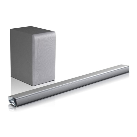
Wireless Sound Bar
SERVICE MANUAL
MODEL: GX / SPN5-W
CAUTION
BEFORE SERVICING THE UNIT, READ THE "SAFETY PRECAUTIONS"
IN THIS MANUAL.
P/NO : AFN30024644
JUNE, 2020
"Any reproduction, duplication, distribution (including by way of email, facsimile or other
electronic means), publication, modification, copying or transmission of this Service Manual is
STRICTLY PROHIBITED unless you have obtained the prior written consent of the LG Electronics
entity from which you received this Service Manual. The material covered by this prohibition includes,
without limitation, any text, graphics or logos in this Service Manual."
Copyright © 2020 LG Electronics Inc. All rights reserved.
Only for training and service purposes.
Advertisement
Table of Contents

Related Manuals for LG GX / SPN5-W


Summary of Contents for LG GX / SPN5-W
- Page 1 Service Manual is STRICTLY PROHIBITED unless you have obtained the prior written consent of the LG Electronics entity from which you received this Service Manual. The material covered by this prohibition includes, without limitation, any text, graphics or logos in this Service Manual.”...
- Page 2 SECTION 1 ..GENERAL SECTION 2 ..CABINET & MAIN CHASSIS SECTION 3 ..ELECTRICAL SECTION 4 ..WIRELESS SUBWOOFER PART SECTION 5 ..WIRELESS RECEIVER PART (OPTION) Copyright © 2020 LG Electronics Inc. All rights reserved. Only for training and service purposes.
-
Page 3: Table Of Contents
• GENERAL SERVICING PRECAUTIONS • INSULATION CHECKING PRODEDURE • ELECTROSTATICALLY SENSITIVE (ES) DEVICES HIDDEN KEY MODE ............................1-5 SOFTWARE UPDATE GUIDE ........................... 1-6 SPECIFICATIONS ............................1-14 Copyright © 2020 LG Electronics Inc. All rights reserved. Only for training and service purposes. -
Page 4: Product Safety Servicing Guidelines For Audio Products
When servicing this product, under no circumstances should the original design be modified or altered without permission from LG Corporation. All components should be replaced only with types identical to those in the original circuit and their physical location, wiring and lead dress must conform to original layout upon completion of repairs. -
Page 5: Servicing Precautions
Note 1: Accessible Conductive Parts include Metal panels, tricity sufficient to damage an ES device.) Input terminals, Earphone jacks,etc. Copyright © 2020 LG Electronics Inc. All rights reserved. Only for training and service purposes. -
Page 6: Hidden Key Mode
Main unit 'VOL-' + Remote Control ' EEPROM CLEAR (Initialize) Main unit 'VOL-' + Remote Control ' VERSION CHECK Main unit 'VOL-' + Remote Control 'Play/Pause' Copyright © 2020 LG Electronics Inc. All rights reserved. Only for training and service purposes. -
Page 7: Software Update Guide
<Android Device> Necessary for USB update “Music Flow Bluetooth” must be installed for FOTA update Caution : • Take care not to power off during update. Copyright © 2020 LG Electronics Inc. All rights reserved. Only for training and service purposes. - Page 8 Verify whether USB function is or not by VFD. (VFD Model) Step 7. Attach USB which has update binaries to the USB slot of GX main unit. 500 mA Copyright © 2020 LG Electronics Inc. All rights reserved. Only for training and service purposes.
- Page 9 Step 11. Check the current versions to verify whether the update was successfully completed or not. <VFD Model> 1) Press “Version Check” hidden key • Version Check Hidden Key : Press Set “Vol-” + RCU “Play/Pause” for 3secs. Copyright © 2020 LG Electronics Inc. All rights reserved. Only for training and service purposes.
- Page 10 Wireless Rear Tx RR1850010 Wireless Rear Rx 00 55 1A 44 ... Option <GX VFD version display> 3) Compare the version VFD shows and you updated. Copyright © 2020 LG Electronics Inc. All rights reserved. Only for training and service purposes.
- Page 11 Step 3. Execute “Music Flow Bluetooth” App. Step 4. Connect between android device and GX main unit by “Music Flow Bluetooth” App. 1-10 Copyright © 2020 LG Electronics Inc. All rights reserved. Only for training and service purposes.
- Page 12 Current version and Latest version in pop up window “Device version info.” are same. Also update icon must be disabled. 1-11 Copyright © 2020 LG Electronics Inc. All rights reserved. Only for training and service purposes.
- Page 13 “Music Flow Bluetooth” LED Model Current Function Function LEDs blink sequentially one by one from left to right. B-UP DNLD VFD Model Current Function M-UP 1-12 Copyright © 2020 LG Electronics Inc. All rights reserved. Only for training and service purposes.
- Page 14 Step 10. Power on GX main unit again. Step 11. Check the current versions to verify whether the update was successfully completed in such a way of Step 5.~ 6. 1-13 Copyright © 2020 LG Electronics Inc. All rights reserved. Only for training and service purposes.
-
Page 15: Specifications
Approx. 100.0 mm x 140.0 mm x 100.0 mm (3.9 inch x 5.5 inch x 3.9 inch) • Designs and specifications are subject to change without prior notice. 1-14 Copyright © 2020 LG Electronics Inc. All rights reserved. Only for training and service purposes. - Page 16 2. HOW TO DISASSEMBLE THE SUBWOOFER ..................2-9 EXPLODED VIEWS ............................2-13 1. MAIN UNIT (GX) SECTION ........................2-13 2. WIRELESS SUBWOOFER (SPN5-W) SECTION .................. 2-17 3. PACKING ACCESSORY SECTION ....................... 2-21 Copyright © 2020 LG Electronics Inc. All rights reserved. Only for training and service purposes.
-
Page 17: Disassembly Instructions
DISASSEMBLY INSTRUCTIONS 1. HOW TO DISASSEMBLE THE MAIN UNIT 1) Chamber no. 1 2) Chamber no. 2 3) MAIN PCB 4) AMP PCB Copyright © 2020 LG Electronics Inc. All rights reserved. Only for training and service purposes. -
Page 18: How To Disassemble The Main Unit
HOW TO DISASSEMBLE THE MAIN UNIT 1) Remove the 10 screws. (1SZZR-0097X) 2) Disconnect the SPK cable and Pull out the SPK. Copyright © 2020 LG Electronics Inc. All rights reserved. Only for training and service purposes. - Page 19 1) Remove the 4 screws. (1SZZR-0098H) 2) Disconnect the FFC cable. 2) Disconnect the SPK cable and Pull out the SPK. 3) Remove the Front PCB Copyright © 2020 LG Electronics Inc. All rights reserved. Only for training and service purposes.
- Page 20 1) When disconnecting the woofer speaker cable, disconnect it by pressing it as shown. 1) Remove the 9 screws. (1SZZR-0098J) 2) Remove the 2 screws. (353-022S) Copyright © 2020 LG Electronics Inc. All rights reserved. Only for training and service purposes.
- Page 21 HOW TO DISASSEMBLE THE MAIN UNIT 1) Remove the 8 screws. (1SZZR-0097X) and disconnect the SPK cable. 2) Pull out the No. 2 Chamber. Copyright © 2020 LG Electronics Inc. All rights reserved. Only for training and service purposes.
- Page 22 HOW TO DISASSEMBLE THE MAIN UNIT 1) Remove the 8 screws. (1SZZR-0097X) and disconnect the SPK cable. 2) Pull out the No.1 Chamber. Copyright © 2020 LG Electronics Inc. All rights reserved. Only for training and service purposes.
- Page 23 HOW TO DISASSEMBLE THE MAIN UNIT 1) Remove the 3 screws. (1SZZR-0098H) 2) Remove the 21 screws. (FAB31442101) 3) Remove the button PCB. Copyright © 2020 LG Electronics Inc. All rights reserved. Only for training and service purposes.
- Page 24 1) Remove the 8 screws. Figure 2-1 (1) 2) Pull out the Rear Panel Assembly and disconnect the SPK cable. Rear Panel Assembly SPK cable Figure 2-1 (2) Copyright © 2020 LG Electronics Inc. All rights reserved. Only for training and service purposes.
-
Page 25: How To Disassemble The Subwoofer
1) Attach the EVA gaskets (1.0T) to both sides of the WIRELESS module. 2) Assemble the WIRELESS module into the wireless holder. Figure 2-2 (2) 2-10 Copyright © 2020 LG Electronics Inc. All rights reserved. Only for training and service purposes. - Page 26 1) Disconnect the Power inlet socket cable. AMP+SMPS PCB Assembly Figure 2-3 (1) 2) Remove the 5 screws. 3) Remove the AMP+SMPS PCB Assembly. AMP+SMPS PCB Assembly Figure 2-3 (2) 2-11 Copyright © 2020 LG Electronics Inc. All rights reserved. Only for training and service purposes.
- Page 27 2-12 Copyright © 2020 LG Electronics Inc. All rights reserved. Only for training and service purposes.
-
Page 28: Exploded Views
EXPLODED VIEWS 1. MAIN UNIT (GX) SECTION A80R CABLE1 WIRELESS CABLE4 A80L CABLE3 MAIN CABLE6 CABLE2 CABLE5 CABLE7 WIRELESS LCD01 CABLE8 2-13 2-14 Copyright © 2020 LG Electronics Inc. All rights reserved. Only for training and service purposes. - Page 29 26P050C-H02-0F01A-N 40MM 0.50M CABLE6 EAD65850901 Cable,FFC 60P050C-H02-0F01AS-N 120MM 0.5 CABLE7 EAD64128906 Cable,FFC 14P050C-H02-1F01A-T 180MM 0.50 CABLE8 EBR31180001 PCB Assembly,Sub SNX7 Center Network Cable [emp 2-15 2-16 Copyright © 2020 LG Electronics Inc. All rights reserved. Only for training and service purposes.
-
Page 30: Wireless Subwoofer (Spn5-W) Section
2. WIRELESS SUBWOOFER (SPN5-W) SECTION A900 A45W A54W 2-17 2-18 Copyright © 2020 LG Electronics Inc. All rights reserved. Only for training and service purposes. - Page 31 WL1NB6_ 0DBM 0DB 0% 0A 0A 0DB AGL30012602 Panel Assembly,Rear SPN5B-W SN5Y Panel Rear Assy EAD62131539 Cable,FFC 26P050D-H01-1F01A-N 60-22-38 6 EAG63233208 Socket,Power DAC-18JN08 2P STRAIGHT WIRE BK 2-19 2-20 Copyright © 2020 LG Electronics Inc. All rights reserved. Only for training and service purposes.
-
Page 32: Packing Accessory Section
839 Stands 823 HDMI cable 900 Remote control 300 Power cord (Main unit) 833 AC adapter 300W Power cord (Woofer) 835 Wall bracket (2) 2-21 Copyright © 2020 LG Electronics Inc. All rights reserved. Only for training and service purposes. - Page 33 HX995 SWCH 10A SPECIAL + 4mM 3 MEG62598701 Holder MOLD ABS HOME THEATER HX995 MO ABA30020902 Bracket Assembly SPK GX Bracket ASSY Stand AKB75595331 Remote Controller Assembly MA6 SM/SL10/9/8/7/6/5/4 Soundb 2-22 Copyright © 2020 LG Electronics Inc. All rights reserved. Only for training and service purposes.
- Page 34 2. AMP P. C. BOARD DIAGRAM ......................3-25 3. FRONT P. C. BOARD DIAGRAM ......................3-27 4. USB P. C. BOARD DIAGRAM ......................3-27 5. KEY P. C. BOARD DIAGRAM ......................3-27 Copyright © 2020 LG Electronics Inc. All rights reserved. Only for training and service purposes.
-
Page 35: Wiring Diagram
WIRING DIAGRAM Copyright © 2020 LG Electronics Inc. All rights reserved. Only for training and service purposes. -
Page 36: Block Diagram
BLOCK DIAGRAM Copyright © 2020 LG Electronics Inc. All rights reserved. Only for training and service purposes. -
Page 37: One Point Repair Guide
3) If 25 VA is OK, but 12 VA is abnormal at pin3 L611 of IC604 (VOUT), IC604 block has problem. 1-1-3. Service hint (Any picture / Remark) IC604 IC604 L611 L611 < AMP board top view > Copyright © 2020 LG Electronics Inc. All rights reserved. Only for training and service purposes. - Page 38 1.5M NC DGND VOUT = 0.798x(70.2K/13K+1)= 5.107V DGND L303 L303 IC302 IC302 < MAIN board top view > Copyright © 2020 LG Electronics Inc. All rights reserved. Only for training and service purposes.
- Page 39 2.7K R324 (1%) (1%) R328 1.5M NC DGND VOUT = 0.798x(41.7K/13K+1)= 3.36V DGND L310 L310 IC311 IC311 < MAIN board top view > Copyright © 2020 LG Electronics Inc. All rights reserved. Only for training and service purposes.
- Page 40 TPF5 VB0- TPF6 VLCD RF03 CNF01 TPF8 0.33uF DGND TPF7 TPF7 pin14 pin14 VCC_5V VCC_5V CNF01 CNF01 < FRONT board bottom view > Copyright © 2020 LG Electronics Inc. All rights reserved. Only for training and service purposes.
-
Page 41: Sound
BT_WAKEUP BT_WAKEUP TP249 R244 GPIO BT_STBY C270 C271 C272 100nF 100pF 100pF TP250 ZD202 DGND CN202 CN202 < MAIN board top view > Copyright © 2020 LG Electronics Inc. All rights reserved. Only for training and service purposes. - Page 42 100nF 10uF R257 OPT_DET VOUT C282 15pF C283 100pF DGND DGND R256 R256 FB200 FB200 < MAIN board bottom view > Copyright © 2020 LG Electronics Inc. All rights reserved. Only for training and service purposes.
- Page 43 I_LIM : 0.2 ~ 2 [A] R301 I_LIM [A] = 230[V]/R_SET[ohm] = 230/R3A2 4.7K DGND IC303 IC303 < MAIN board top view > 3-10 Copyright © 2020 LG Electronics Inc. All rights reserved. Only for training and service purposes.
- Page 44 @pinCo DGND @pinCo @pinCo TPK09 @pinCo CNK01 TPK01 CNK02 @pinCo @pinCo @pinCo @pinCo DGND JKK01 JKK01 < USB board top view > 3-11 Copyright © 2020 LG Electronics Inc. All rights reserved. Only for training and service purposes.
-
Page 45: Protection Error
4) If PWM IC out is ok and speaker out (FL+/-, FR+/-, TL+/-, TR+/-, C+/-) has DC voltage, then replace AMP board. 3-1-3. Service hint (Any picture / Remark) CN702 CN702 CN703 CN703 CN704 CN704 < AMP board bottom view > 3-12 Copyright © 2020 LG Electronics Inc. All rights reserved. Only for training and service purposes. - Page 46 2) If 12 V is OK, replace AMP board. 3-2-3. Service hint (Any picture / Remark) IC700 IC700 IC701 IC701 IC702 IC702 < AMP board top view > 3-13 Copyright © 2020 LG Electronics Inc. All rights reserved. Only for training and service purposes.
-
Page 47: Waveforms Of Major Check Point
R1C0 4.7K 4.7K 4.7K R1C1 C163 4.7K 100nF MSF_SPI_CS /16V HOLD# MSF_MISO DGND SCLK MSF_CLK MSF_MOSI EQ_GIGA DGND FIG 2. VCC, CS#, CLK, DO 3-14 Copyright © 2020 LG Electronics Inc. All rights reserved. Only for training and service purposes. -
Page 48: Usb
UPPER SIDE TP297 TP251 TP242 TP252 R260 USB_DM_P0 TP243 TP253 R255 USB_DP_P0 TP298 TP254 FL211 C278 C279 10pF 10pF TP299 CN204 TP207 DGND R207 3-15 Copyright © 2020 LG Electronics Inc. All rights reserved. Only for training and service purposes. -
Page 49: Remote Control
“ Low” Timing 4.52 ms 3.6 ~ 5.04 ms “ High” Timing 4.45 ms 4.08 ~ 5.04 ms FIG 4-3. High Timing IR Receiver Spec 3-16 Copyright © 2020 LG Electronics Inc. All rights reserved. Only for training and service purposes. -
Page 50: Optical
M_OPT_IN R293 C290 100nF 3.3V_OPT FET SWITCH DGND DGND JK202 Select C281 C280 100nF 10uF R257 OPT_DET VOUT C282 15pF C283 100pF DGND DGND 3-17 Copyright © 2020 LG Electronics Inc. All rights reserved. Only for training and service purposes. - Page 51 3-18 Copyright © 2020 LG Electronics Inc. All rights reserved. Only for training and service purposes.
-
Page 52: Circuit Voltage Chart
1.425~1.575 V 1.5 V AD22, AD23 …. AVDD33 3.15~3.45 V 3.3 V A6, Y8 AVDD18 1.71~1.89 V 1.8 V AVDD105 0.99~1.10 V 1.0 V 3-19 3-20 Copyright © 2020 LG Electronics Inc. All rights reserved. Only for training and service purposes. -
Page 53: Capacitor Voltage
3.36 V 3.35 V 3.3 VA(3.0~3.6 V) CN204 / CNK01 (MAIN <-> USB) POWER MAIN SPEC. USB_5V 5.19 V 5.19 V 5.0 V(4.75~5.25 V) 3-21 3-22 Copyright © 2020 LG Electronics Inc. All rights reserved. Only for training and service purposes. -
Page 54: Printed Circuit Board Diagrams
PRINTED CIRCUIT BOARD DIAGRAMS 1. MAIN P. C. BOARD DIAGRAM (TOP VIEW) (BOTTOM VIEW) 3-23 3-24 Copyright © 2020 LG Electronics Inc. All rights reserved. Only for training and service purposes. -
Page 55: Amp P. C. Board Diagram
2. AMP P. C. BOARD DIAGRAM (TOP VIEW) (BOTTOM VIEW) 3-25 3-26 Copyright © 2020 LG Electronics Inc. All rights reserved. Only for training and service purposes. -
Page 56: Front P. C. Board Diagram
(TOP VIEW) (BOTTOM VIEW) 4. USB P. C. BOARD DIAGRAM (TOP VIEW) (BOTTOM VIEW) 5. KEY P. C. BOARD DIAGRAM (TOP VIEW) (BOTTOM VIEW) 3-27 3-28 Copyright © 2020 LG Electronics Inc. All rights reserved. Only for training and service purposes. - Page 57 3-29 3-30 Copyright © 2020 LG Electronics Inc. All rights reserved. Only for training and service purposes.
- Page 58 6. LED ............................... 4-11 CIRCUIT VOLTAGE CHART ........................... 4-13 PRINTED CIRCUIT BOARD DIAGRAMS ....................... 4-15 1. WOOFER SMPS & AMP P. C. BOARD ....................4-15 Copyright © 2020 LG Electronics Inc. All rights reserved. Only for training and service purposes.
-
Page 59: Wiring Diagram
WIRING DIAGRAM 2P, 3.96mm ST, Non Lock SMD Wireless 26P, 0.5mm ST, Non Lock SMD 2P, 3.96mm ST, Non Lock , SMD Power Copyright © 2020 LG Electronics Inc. All rights reserved. Only for training and service purposes. -
Page 60: Block Diagram
BLOCK DIAGRAM Wireless LED (RED, GREEN) Wireless AMP_PDN AMP_SD PAIRING Reset KEY SW+/SW- PWM IC AMP IC Copyright © 2020 LG Electronics Inc. All rights reserved. Only for training and service purposes. -
Page 61: One Point Repair Guide
If you can’t check 12 VA voltage, refer to the step 1-1. WL707 WL707 WIC705 WIC705 < Woofer SMPS & AMP board top view > Copyright © 2020 LG Electronics Inc. All rights reserved. Only for training and service purposes. - Page 62 3) 1), 2) is NG Replace WIC703. If you can’t check PVDD voltage, then replace the PCB board. WIC703 WIC703 < Woofer SMPS & AMP board bottom view > Copyright © 2020 LG Electronics Inc. All rights reserved. Only for training and service purposes.
-
Page 63: Wireless Connection
The main set and the wireless subwoofer are factory reset mode, then power on. WFB604 WFB604 Wireless module Wireless module Connection check Connection check < Woofer SMPS & AMP board top view > Copyright © 2020 LG Electronics Inc. All rights reserved. Only for training and service purposes. -
Page 64: Waveforms Of Major Check Point
WAVEFORMS OF MAJOR CHECK POINT 1. CRYSTAL FIG 1. WX601 (24.576 MHz) 2. FLASH MEMORY FIG 2. VCC, CS#, CLK, DO Copyright © 2020 LG Electronics Inc. All rights reserved. Only for training and service purposes. -
Page 65: Voltage
3. VOLTAGE FIG 3-2. Woofer 12 VA FIG 3-1. Woofer PVDD FIG 3-3. Woofer 3.3 VA FIG 3-4. Woofer 3.3V_PWM Copyright © 2020 LG Electronics Inc. All rights reserved. Only for training and service purposes. -
Page 66: Amp Voltage
4. AMP VOLTAGE FIG 4-2. AMP_12V FIG 4-1. AMP PVDD Copyright © 2020 LG Electronics Inc. All rights reserved. Only for training and service purposes. -
Page 67: Pwm
5. PWM FIG 5-2. Woofer PWM SW- Signal FIG 5-1. Woofer PWM SW+ Signal 4-10 Copyright © 2020 LG Electronics Inc. All rights reserved. Only for training and service purposes. -
Page 68: Led
6. LED FIG 6-2. Pairing On Status Green LED FIG 6-1. Pairing Off Status Red LED 4-11 Copyright © 2020 LG Electronics Inc. All rights reserved. Only for training and service purposes. - Page 69 4-12 Copyright © 2020 LG Electronics Inc. All rights reserved. Only for training and service purposes.
-
Page 70: Circuit Voltage Chart
12.52 V 12.52 V 4.5 V ~ 17 V WIC705 DC,DC Converter VOUT: SW: #2 3.42 V 3.42 V 0.76 V ~ 7 V 4-13 4-14 Copyright © 2020 LG Electronics Inc. All rights reserved. Only for training and service purposes. -
Page 71: Printed Circuit Board Diagrams
1. WOOFER SMPS & AMP P. C. BOARD (TOP VIEW) (BOTTOM VIEW) NOTE) Warning Parts that are critical with respect to risk of fire or electrical shock. 4-15 4-16 Copyright © 2020 LG Electronics Inc. All rights reserved. Only for training and service purposes. - Page 72 WAVEFORMS ..............................5-7 PRINTED CIRCUIT BOARD DIAGRAMS ......................5-9 1. WIRELESS RECEIVER SMPS P. C. BOARD ..................5-9 2. WIRELESS RECEIVER AMP P. C. BOARD ..................5-11 Copyright © 2020 LG Electronics Inc. All rights reserved. Only for training and service purposes.
-
Page 73: Wiring Diagram
WIRING DIAGRAM Copyright © 2020 LG Electronics Inc. All rights reserved. Only for training and service purposes. -
Page 74: Block Diagram
BLOCK DIAGRAM Wireless LED (RED, GREEN) Wireless AMP_PDN AMP_SD PAIRING R R eset KEY RL+,-/RR+,- PWM IC Copyright © 2020 LG Electronics Inc. All rights reserved. Only for training and service purposes. -
Page 75: One Point Repair Guide
Check 3.3 V. Replace AMP board. 2-3. Service hint (Any picture / Remark) RIC308 RIC308 RIC308 RIC307 RIC307 RIC307 < AMP board top view > Copyright © 2020 LG Electronics Inc. All rights reserved. Only for training and service purposes. - Page 76 Check Module or connection. Replace AMP board. 3-3. Service hint (Any picture / Remark) RIC308 RIC308 RIC308 RIC307 RIC307 RIC307 < AMP board top view > Copyright © 2020 LG Electronics Inc. All rights reserved. Only for training and service purposes.
-
Page 77: Electrical Troubleshooting Guide
(RCN301 pin9, 10) no output. AMP 12 V (RIC308 pin4) Check RIC308. no output. 3.3 V (RIC307 pin3) Check RIC307. no output. Check Module or Connection. Copyright © 2020 LG Electronics Inc. All rights reserved. Only for training and service purposes. -
Page 78: Waveforms
WAVEFORMS 1. AUDIO PART (I2S) RCN303 pin1 : I2S LRCK RCN303 pin3 : I2S BCK RCN303 pin20 : I2S Audio Data Copyright © 2020 LG Electronics Inc. All rights reserved. Only for training and service purposes. - Page 79 Copyright © 2020 LG Electronics Inc. All rights reserved. Only for training and service purposes.
-
Page 80: Printed Circuit Board Diagrams
1. WIRELESS RECEIVER SMPS P. C. BOARD (TOP VIEW) (BOTTOM VIEW) NOTE) Warning Parts that are critical with respect to risk of fire or electrical shock. 5-10 Copyright © 2020 LG Electronics Inc. All rights reserved. Only for training and service purposes. -
Page 81: Wireless Receiver Amp P. C. Board
2. WIRELESS RECEIVER AMP P. C. BOARD (TOP VIEW) (BOTTOM VIEW) 5-11 5-12 Copyright © 2020 LG Electronics Inc. All rights reserved. Only for training and service purposes.
Need help?
Do you have a question about the GX / SPN5-W and is the answer not in the manual?
Questions and answers