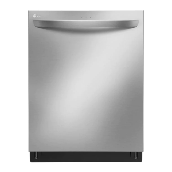
LG LDT7797 Series Service Manual
Hide thumbs Also See for LDT7797 Series:

Advertisement

DISHWASHER
SERVICE MANUAL
NOTE
Read this manual caRefully befoRe seRvicing the pRoduct. follow
the manual's instRuctions when seRvicing the pRoduct.
For Authorized Service Technicians
MODEL : LUDP8997SN / LDT7797** / LDP6797** / LDP5676** /
Any reproduction or duplication (including by way of email, facsimile or other electronic means),
publication, modification, copying or transmission of this Service Manual is STRICTLY PROHIBITED unless you
have obtained the prior written consent of the LG Electronics entity from which you received this Service
Manual. The material covered by prohibition includes, without limitation, any text, graphics or logos in this
Service Manual.
Copyright ⓒ 2017 - 21 LG Electronics Inc. All rights
reserved. Only for training and service purposes.
LDT5665** / LDF5545** / LSDF9897** / LDT7808** /
LSDT9908** / LDT5678** / LDF5678** / LDP7708** /
SKSDW24*** / LDB4548** / LDT6809** / LDP6809** /
LDPS6844** / LDP7808** / LDP6810** / LUDP8908**
LDFN343** / LDTS555** / LSDTS988** / LDFN454**
CONFIDENTIAL

Advertisement

Table of Contents
loading

Summary of Contents for LG LDT7797 Series

  • Page 1 Service Manual is STRICTLY PROHIBITED unless you have obtained the prior written consent of the LG Electronics entity from which you received this Service Manual. The material covered by prohibition includes, without limitation, any text, graphics or logos in this Service Manual.
  • Page 3: Table Of Contents

    For Authorized Service Technicians CONTENTS 1. impoRtant safety notice ........................... 4 2. specifications ................................5 3. featuRes and opeRation ............................ 6 4. paRts ....................................32 5. pRogRam chaRts ..............................34 6. how to disassemble ............................42 7. tRoubleshooting methods .......................... 62 7-1.
  • Page 4: Important Safety Notice

    For Authorized Service Technicians CAUTION DISCONNECT POWER SUPPLY LINE BEFORE SERVICING RECONNECT ALL GROUNDING DEVICES IMPORTANT SAFETY NOTICE This service information is intended for individuals possessing adequate backgrounds of electrical, electronic and mechanical experience. Any attempt to repair this appliance may result in personal injury and property damage.
  • Page 5: Specifications

    For Authorized Service Technicians 2. SPECIFICATIONS ITEM SPECIFICATION Rated voltage / frequency ac 120v/60hz installation built-in place settings product dimension (in.) (w) x 24 ⅝ (d) x 33 ⅝ (h) product weight (lb.) 72-97 door color white, black, stainless steel, black sts, matte black tub material stainless steel control...
  • Page 6: Features And Operation

    LG ThinQ™ Download the new LG smart phone app to set options, self-diagnose and troubleshoot problems with the appliance, and other useful features. Some of these functions use Wi-Fi or NFC (Near Field Communication) technology and require an NFC-equipped smart phone.
  • Page 7 For Authorized Service Technicians Control Panel for non-steam models (ldt779#**, ldp679#**, ldp567#**, ldt566#**, ldt5678**, ldf5678**) before 106xx Power • : Control Lock • Press the Power button to turn power on and - The Control Lock feature helps prevent off. settings from being changed during a cycle.
  • Page 8 For Authorized Service Technicians Control Panel for non-steam models (ldt779#**, ldp679#**, ldp567#**, ldt566#**, ldt5678**, ldf5678**) after 106xx Power : Machine Clean & Sanitized Icon • • Press the Power button to turn power on and off. - Machine Clean This cycle is for cleaning the inside of the •...
  • Page 9 For Authorized Service Technicians Control Panel for non-steam models (ldf554#**) before 705xx Power • : Control Lock • Press the Power button to turn power on and - The Control Lock feature helps prevent off. settings from being changed during a cycle. Selecting this feature locks all of the buttons, •...
  • Page 10 For Authorized Service Technicians Control Panel for non-steam models (ldf554#**, ldb4548**) between 705xx ~ 105xx Power • : Control Lock • Press the Power button to turn power on and - The Control Lock feature helps prevent off. settings from being changed during a cycle. •...
  • Page 11 For Authorized Service Technicians Control Panel for non-steam models (ldf554#**, ldb4548**) after 106xx Power : Control Lock • • Press the Power button to turn power on and - The Control Lock feature helps prevent off. settings from being changed during a cycle. •...
  • Page 12 For Authorized Service Technicians Cycles Download Cycle Before 106XX Use a dedicated cycle downloadable via Wi-Fi or Select your desired cycle. NFC. Auto Machine Clean This cycle senses the soil amount and soil toughness This cycle is for cleaning the inside of the dishwasher. and is optimized to achieve the best cleaning.
  • Page 13 For Authorized Service Technicians Options High Temp Before 106XX Select the desired cycle button and then select the Raises the main wash temperature to improve options for that cycle. cleaning. Extra Dry Dual Zone Select the Extra Dry option for better drying This option automatically sets the spray intensity to performance.
  • Page 14 For Authorized Service Technicians Cycles Download Cycle After 106XX Use a dedicated cycle downloadable via Wi-Fi or Select your desired cycle. NFC. NOTE Auto • Only the cycle code for the current Download cycle This cycle senses the soil amount and soil toughness appears on the appliance.
  • Page 15 For Authorized Service Technicians Options High Temp After 106XX Select the desired cycle button and then select the Raises the main wash temperature to improve options for that cycle. cleaning. If the High Temp option is added to a cycle, the indicator stays lit at the end of the cycle if the Dual Zone...
  • Page 16 For Authorized Service Technicians Control Panel For Steam Models(LSDF9897**, LDT7808**, LSDT9908**, LDP7708**, SKSDW24***, LDT6809**, LDP6809**, LDPS6844**, LDP7808**, LDP6810**, LDTS555**) Before 106XX Power • : Rinse Aid Icon • Press the Power button to turn power on and - This icon illuminates when the rinse aid level is off.
  • Page 17 For Authorized Service Technicians Cancel • The drain pump activates and the cycle cancels. power turns off. • Press and hold Start for three seconds to activate. Start • To operate the machine, either press Start and close the door within four seconds or close the door and press Start.
  • Page 18 For Authorized Service Technicians Cycles Download Cycle Before 106XX Use a dedicated cycle downloadable via Wi-Fi or Select your desired cycle. NFC. Auto NOTE • Only the cycle code for the current Download cycle This cycle senses the soil amount and soil toughness appears on the appliance.
  • Page 19 For Authorized Service Technicians Options High Temp Before 106XX Raises the main wash temperature to improve Select the desired cycle button and then select the cleaning. options for that cycle. Extra Dry Dual Zone Select the Extra Dry option for better drying This option automatically sets the spray intensity to performance.
  • Page 20 For Authorized Service Technicians Control Panel for steam models(lsdf9897**, ldt7808**, lsdt9908**, ldp7708**, sKsdw24***, ldt6809**, ldp6809**, ldps6844**, ldp7808**, ldp6810**, ldts555**, lsdts988**) after 106xx Power • : Rinse Aid Icon • Press the Power button to turn power on and - This icon illuminates when the rinse aid level is off.
  • Page 21 For Authorized Service Technicians Cancel • The drain pump activates and the cycle cancels. Once the dishwasher finishes draining, the power turns off. • Press and hold Start for three seconds to activate. Start • To operate the machine, either press Start and close the door within four seconds or close the door and press Start.
  • Page 22 For Authorized Service Technicians Cycles Download Cycle After 106XX Use a dedicated cycle downloadable via Wi-Fi or Select your desired cycle. NFC. Auto NOTE • Only the cycle code for the current Download cycle This cycle senses the soil amount and soil toughness appears on the appliance.
  • Page 23 For Authorized Service Technicians Options High Temp After 106XX Raises the main wash temperature to improve Select the desired cycle button and then select the cleaning. options for that cycle. Extra Dry Dual Zone Select the Extra Dry option for better drying This option automatically sets the spray intensity to performance.
  • Page 24 For Authorized Service Technicians Control Panel For Steam Models(LUDP8908**) Power Control Lock • Press the Power button to turn power on and off. The Control Lock feature helps prevent settings from being changed during a cycle. Selecting this feature • After the cycle is complete, the power automatically locks all of the buttons, except for the Power button, turns off for purposes of safety and economy.
  • Page 25 For Authorized Service Technicians Cycles Download Cycle Use a dedicated cycle downloadable via Wi-Fi or Select your desired cycle. NFC. Auto NOTE • Only the cycle code for the current Download cycle This cycle senses the soil amount and soil toughness appears on the appliance.
  • Page 26 For Authorized Service Technicians Options High Temp Raises the main wash temperature to improve Select the desired cycle button and then select the cleaning. options for that cycle. Extra Dry Dual Zone Select the Extra Dry option for better drying This option automatically sets the spray intensity to performance.
  • Page 27 For Authorized Service Technicians Control Panel For Models(LDFN343**) Control Panel Features Power On/Off Button • Press this button to turn the washer on or off. • If there is a power surge, power outage, or disruption of any kind, power is automatically turned off for safety.
  • Page 28 For Authorized Service Technicians Chime On/Off Button • To activate or deactivate the button sounds, press and hold Cycles and Machine Clean simultaneously for three seconds. The error alert sound cannot be turned off. Cancel Button • The drain pump activates and the cycle cancels. Once the dishwasher finishes draining, the power turns off.
  • Page 29 For Authorized Service Technicians Night Dry Mode Description Dishes are often left in the dishwasher overnight Various conditions after the cycle ends. This can result in the steam • Place heavily soiled dishes like inside the tub condensing on dishes, leaving them plates and bowls in the lower rack wet.
  • Page 30 For Authorized Service Technicians 3-3. TEST MODE CHECK PROGRAM Before 106XX Times Load and Checking points Door BUTTON button is Top Display open/ Remark Load LED lighting pushed closed "nC" will be n35/U00/ POWER All LEDs are displayed when 1 TIME Either +START NFC or Wifi Module...
  • Page 31 For Authorized Service Technicians 3-3. TEST MODE CHECK PROGRAM After 106XX Times Load and Checking points Door BUTTON button is Top Display open/ Remark Load LED lighting pushed closed "nC" will be POWER n35/U00/ All LEDs are displayed when +START 1 TIME Either NFC or Wifi Module...
  • Page 32: Parts

    For Authorized Service Technicians 4. PARTS Exterior Parts Control Panel & Door Handle Control Panel Front Cover Door Handle Lower Cover Front Cover Shipping Brace Lower Cover Safety Cover Shipping Brace SignaLight™ (some models) Safety Cover Base SignaLight™ (some models) Leveling Feet Base Leveling Feet...
  • Page 33 For Authorized Service Technicians Exterior Parts For Models : LDFN343** Control Panel & Door Handle Front Cover Lower Cover Leveling Feet Base Safety Cover Shipping Brace Interior Parts For Models : LDFN343** Top Wash Impeller Upper Spray Arm Lower Spray Arm Filtration System Detergent and Rinse Aid Dispenser Drying Vent Cover...
  • Page 34: Program Charts

    For Authorized Service Technicians 5. PROGRAM CHARTS (SCHEMATIC DIAGRAMS) C10 C11 C13 C14 C15 C16 C17 C18 C19 C20 C28 C29 C30 C38 C39 C40 C41 C42 C43 C44 C45 C46 C47 C48 C49 C50 C51 C52 C53 C54 C55 C56 C57 C58 C59 C60 C61 C62 C63 C68 C69 C70 Large Class Medium Class...
  • Page 35 For Authorized Service Technicians C83 C84 C85 C86 C87 C88 C89 C90 C91 C92 C93 C94 C95 C96 C97 C98 C99 C10 C101 C10 C103 C10 C105 C10 C107 C10 C109 C11 C111 C11 C113 C11 C115 C116 C117 C118 C119 C120 C121 C122 C123 C124 C125 C126 C127 C128 C12 C130 C13 C132 C13 C134 C13 C136 C13 C138 C13 C140 C14 C142 C14 C144 C14 C146 C14 C148 C14 C150 C151 C152 C153 C154 C155 C156 C157 C15 C159 C16...
  • Page 36 For Authorized Service Technicians C161 C16 C163 C16 C165 C16 C167 C16 C169 C17 C171 C17 C173 C17 C175 C17 C177 C17 C179 C180 C181 C182 C183 C184 C185 C186 C18 C188 C18 C190 C19 C192 C19 C194 C19 C196 C19 C198 C19 C200 C20 C202 C20 C204 C20 C206 C20 C208 C20 C210 C21 C212 C213 C214C21 C216 C21 C218 C21 C220 C22 C222 C22...
  • Page 37 For Authorized Service Technicians C244 C245 C246 C247 C248 C249 C250 C251 C252 C253 C254 C255 C256 C257 C258 C259 C260 C261 C262 C263 C264 C265 C266 C267 C268 C269 C270 C271 C272 C273 C274 C275 C276 C277 C278 C279 C280 C281 C282 C283 C284 C285 C286 C287 C288 C289 C290 C291 C292 C293 C294 C295 C296 C297 C298 C299 C300...
  • Page 38 For Authorized Service Technicians C307 C308 C309 C31 C311 C31 C313 C31 C315 C31 C317 C31 C319 C32 C321 C32 C323 C32 C325 C32 C327 C32 C329 C33 C331 C33 C333 C33 C335 C336 C337C33 C339 C34 C341 C34 C343 C34 C345 C346 C347 C348 C349 C350 C351 C352 C353 C354 C355 C356 C357 C358 C359 C360 C361 C362 C363C36 C365 C36 C367 C36 C369 C37 C371 C37 C373 C374 C375 C376 C377 C378 C379 C380 C381 C382 C383 C384 C385C38 C387 C38 C389 C39 Rinse 1...
  • Page 39 For Authorized Service Technicians C391 C39 C393 C39 C395 C396 C397 C398 C399 C400 C401 C402 C403 C404 C405 C406 C407 C408 C409 C41 C411 C41 C413 C41 C415 C41 C417 C41 C419 C42 C421 C42 C423 C42 C425 C42 C427 C42 C429 C43 C431 C43 C433 C43 C435 C43 C437 C43...
  • Page 40 For Authorized Service Technicians C472 C473 C474 C475 C476 C477 C478 C479 C480 C481 C482 C483 C484 C48 C486 C48 C488 C48 C490 C49 C492 C49 C494 C49 C496 C497 C498 C499 C500 C501 C50 C503 C50 C505 C50 C507 C50 C509 C510 C511 C512...
  • Page 41 For Authorized Service Technicians C522 C524 C525C52 C527 C528C52 C530 C531 C532 C533 C534 C535 C536 C537 C538 C539 C540 C541 C542 C543 C544 C545 C546 C547 C548 C549 C550 C551 C552 C553 C554 C555 C556 C557 C558 C559 C560 C561 C562 C563...
  • Page 42: How To Disassemble

    For Authorized Service Technicians 6. HOW TO DISASSEMBLE 1. Lower Cover 1) Remove the front 2 screws. ※ For models : LUDP8908** (Only models with Toe Kick installed) 1) Slide Toe Kick Assembly from brackets. 2) Remove the front 2 screws and brackets. - 42 -...
  • Page 43 For Authorized Service Technicians 2-1. Front Cover Assembly ※ for models: ludp8997**, ldp6797**, ldp5676**, ldf5545**, ldt5678**, ldf5678**, ldp7708**,ldb4548**, ldp6809**, ldps6844**, ldp7808**, ldp6810**, ludp8908**, ldfn454** ① open the door. ② Remove the 6 screws around front cover assembly. ※ for models: ldt7797**, ldt5665**, lsdf9897**, ldt7808**, lsdt9908**, sKsdw24***,, ldt6809**, ldts555**, lsdts988**...
  • Page 44 For Authorized Service Technicians 2-1. Front Cover Assembly caution caution: take care when disassembling the front Actuator cover to avoid putting stress on the wire harness and dispenser actuator between the front cover and the dispenser.doing so may disconnect the wire harness or dislodge or Dispenser Ha rness Housing...
  • Page 45 For Authorized Service Technicians 2-2. Control Panel Assembly ※ for models: ldp6797**, ldp5676**, ldf5545**, ldt5678**, ldf5678**, ldp7708**, ldb4548**, ldp6809**, ldps6844**, ldp7808**, ldp6810**, ldfn454** ① Remove the 6 screws. ② disconnect the wire connections. ③ Remove the handle.. ※ for model: ludp8997**, ludp8908** Remove front cover screws, then follow steps 1-3 above.
  • Page 46 For Authorized Service Technicians 2-3. Door Liner Assembly blower assembly dispenser fan motor ① Remove the screw. ② Remove the vent from fan motor. ③ disconnect the connector. ④ open the door. ⑤ Remove the blower cover - insert flat head screwdriver in hole (a). - Rotate flat head screwdriver slowly.
  • Page 47 For Authorized Service Technicians dispenser assembly caution: blower cover is easily Dispenser damaged. using dispenser service Jig ① close the door. ② disconnect electrical wire connectors from dispenser. ③ insert the two side pieces into the inside Connector of the dispenser. ④...
  • Page 48 For Authorized Service Technicians 2-4. Door Spring Replacing door spring Roller Rope ① pull the Rope and spring. Spring ② Remove the Rope from the Roller. ③ Remove the spring from the base. Base 2-5. Door Liner Replacing door liner ①...
  • Page 49 For Authorized Service Technicians 3. Lower Frame ① Remove 2 screws. ② press the holder hook as shown in overflow hose figure. ③ Remove the harness holder. ④ Remove the overflow hose from the lower frame. ※ for ludp8997**,ludp8908** model, harness Remove the insulation sheet, then follow holder...
  • Page 50 For Authorized Service Technicians 4. Tub Assembly Removing Racks (2-Rack models) ① slide all racks forward to remove. ※ for this model only (ldt5665**, ldf5545**, ldb4548**) Removing Racks (3-Rack models) ① Remove all Racks. ※ for this model only (ludp8997**, ldt7797**, ldp6797**, ldp5676**, lsdf9897**, ldt7808**, lsdt9908**, ldt5678**, ldf5678**, ldp7708**, sKsdw24***, ldt6809**,...
  • Page 51 For Authorized Service Technicians ※ Removing gliding upper Rack Rear Hook ① insert a tool to widen the space between the hooks at the front of the rack while pulling up on the rack to Front Hook disengage it. ② grab the Rack and push it back to remove rack from 2 rear hooks.
  • Page 52 For Authorized Service Technicians Roller ※ for models: ldfn343** ① press the hook and pull the roller in the direction of the arrow. 2) Removing nozzle & water guides ① Remove the 2 screws on the lower nozzle. ② pull up the lower nozzle and remove. ③...
  • Page 53 For Authorized Service Technicians ※ for models : ※ assembling new lower connector lsdf9897**, ldt7808**, lsdt9908**, ldp7708**, sKsdw24***, ldt6809**, assemble the lower connector ldp6809**, ldps6844**, ldp7808**, properly to the guideline shown here, ludp8908**, lsdts988** and tightly secure the clamp. ※ caution : do not remove the lower water guide.
  • Page 54 For Authorized Service Technicians 3-1) Removing air guide assembly air guide air guide ① turn the air guide nut counterclockwise. ※ take care not to lose the rubber packing around the air guide assembly. ② disconnect the connector. ③ Remove the clamp on the inlet hose. ④...
  • Page 55 For Authorized Service Technicians 6) Removing main pcb ① press the hook and remove the pcb. ② Remove the screw and take the pcb cover off. ③ disconnect the connector. ※ use care and move slowly when pulling out the main pcb. pcb cover main pcb ※...
  • Page 56 For Authorized Service Technicians 7) casing assembly, pump ① lay the product down on the floor. ※ lay down towels first to protect floors from leakage. ② Remove the base cover. ③ Remove the wire on the motor. ④ disconnect the connector. ⑤...
  • Page 57 For Authorized Service Technicians 8-2) Removing hinge supporter ① Remove the hinge supporter screw. ② Remove the hinge supporter from base hook 8-3) Removing Rail assembly (all other models) ① detach the glide Rail from the front hook ② push the glide Rail slightly backwards ③...
  • Page 58 For Authorized Service Technicians 9) Removing sump & base ① Remove the 7 screws on the sump cover. Sump Cover ② Remove the 2 screws on the base. ③ Remove the Roller. Base ④ Remove the hinge supporter from base hook.
  • Page 59 For Authorized Service Technicians 5. Sump Assembly 1) Removing vario motor & cam ① Remove 2 screws for vario motor vario ② pull the vario motor/cam and micro motor switch. vario micro 2) Removing soil sensor switch ① Remove the wire connections. soil ②...
  • Page 60 For Authorized Service Technicians <Steam Model> 1. Sump Assembly 1) Removing steam ball valve ① Remove 2 screws. ② Remove the clamp. ③ pull the steam ball valve. 2) Removing steam nozzle hose ① Remove the front cover. ② Remove the duct. ③...
  • Page 61 For Authorized Service Technicians <Steam Model> 2. Door Liner Assembly 1) steam nozzle ① Remove the 4 screws. ② pull the steam nozzle and bracket. - 61 -...
  • Page 62: Troubleshooting Methods

    For Authorized Service Technicians 7. TROUBLESHOOTING METHODS 7-1. tRoubleshooting accoRding to displayed eRRoR message possible cause eRRoR message Remedy foR eRRoR occuRRence 1) the water supply tap is closed. 1) open the water supply tap. 2) wiring connection is oK? 2) check and reconnect the wire.
  • Page 63 For Authorized Service Technicians 1) the inlet valve is damaged. 1) Replace the inlet valve. EXCESS ERROR 2) the controller is damaged. 2) Replace the controller. 3) after Replace the pcb, still same 3) Replace the hole sensor. error code is displaying. displayed Condition water fills above normal...
  • Page 64: Troubleshooting Methods

    For Authorized Service Technicians 7-2. tRoubleshooting methods How to Check Water supply (LQC Mode) - Press ‘Power + Start’ ※LDFN343** : Press 'Power + Extra Dry + Start' - Press ‘Start’ 5 times. (Check supplying sound) - Press ‘Power’ (Turn off the dishwasher) - 64 -...
  • Page 65 For Authorized Service Technicians Only LDT5678**/LDF5678**/LDP7708**/SKSDW24***/LDB4548**/LDT6809**/ LDP6809**/LDPS6844**/LDP7808**/LDP6810**/LUDP8908** /LDTS555** How to Check Water Supply (LQC Mode) 7-2. tRoubleshooting methods Before 106XX Models : - Press 'POWER + START' ※ LDF5678**/ LDT5678** / LDP6810** : Press 'POWER + AUTO + START'' After 106XX Models : - Press 'POWER + AUTO + START' ※...
  • Page 66 For Authorized Service Technicians - 66 -...
  • Page 67 For Authorized Service Technicians ※ For AE errors, see the checklist below and provide more details on the repair report under Technical Remarks. 1) check that unit is properly leveled. use a digital level to check proper level. 2) check that the mounting bracket is properly installed. 3) determine what kind of detergent and rinse-aid are being used.
  • Page 68 For Authorized Service Technicians - 68 -...
  • Page 69 For Authorized Service Technicians Only LDT5678**/LDF5678**/LDP7708**/SKSDW24***/LDB4548**/LDT6809**/ LDP6809**/LDPS6844**/LDP7808**/LDP6810**/LUDP8908**/LDTS555** - 69 -...
  • Page 70 For Authorized Service Technicians - 70 -...
  • Page 71 For Authorized Service Technicians - 71 -...
  • Page 72 For Authorized Service Technicians - 72 -...
  • Page 73 For Authorized Service Technicians - 73 -...
  • Page 74 For Authorized Service Technicians No Power Is the supplied voltage Check the Reconnect the 120V AC(+10%, -15%) fuse or reset connector or repair Is the connector connected to Main PCB the circuit the harness Assembly disconnected or disassembled? breaker. Replace the Alternate Is Chip LED on while the power is on? main PCB...
  • Page 75 For Authorized Service Technicians Washing result is not satisfactory. After washing, are there white Using a wash booster will help deposits on the dishes or inner remove spots, residue and hard tub? water (white) film. After washing, are there Reduce the amount of Rinse aid. any streaks on the dishes or inner tub? After washing, are there...
  • Page 76 For Authorized Service Technicians Drying result is not satisfactory. After washing, are there Reduce the amount of Rinse aid. any streaks on the dishes or inner tub? After washing, are there Increase the amount of Rinse aid. water drops on the dishes or inner tub? Is the drying result of a) Does the upper nozzle fit properly...
  • Page 77: Trouble Diagnoses And Repair By Symptom

    For Authorized Service Technicians 7-3. TROUBLE DIAGNOSES AND REPAIR BY SYMPTOM No Power on when the power button pressed. • Re-connect the power connection. The Power connection is correctly connected. • Was there a power failure? The Fuse or Circuit Breaker •...
  • Page 78 For Authorized Service Technicians The Wash Pump/Motor does not run. • close the Door tightly. The Door is tightly closed? • Check the Door Switch in Latch Handle. • Re-connect the wiring connections related to the The Wiring connections are OK? Washing Motor.
  • Page 79 For Authorized Service Technicians Power Button not automatically off after operation. Make sure the button is not blocked by foreign materials. Check the Power Switch.(Replace it, if necessary.) Check the Controller.(Replace it, if necessary.) - 28 - - 28 - - 79 -...
  • Page 80: Installation Instructions

    For Authorized Service Technicians 8. INSTALLATION INSTRUCTIONS - 80 -...
  • Page 81 For Authorized Service Technicians - 81 -...
  • Page 82 For Authorized Service Technicians - 82 -...
  • Page 83 For Authorized Service Technicians - 83 -...
  • Page 84 For Authorized Service Technicians - 84 -...
  • Page 85 For Authorized Service Technicians - 85 -...
  • Page 86 For Authorized Service Technicians Connecting Water Supply • The best location for the electrical conduit is on the right side of the back wall. Re-route the electrical Line and Power cable before installation if the electrical conduit pipe is longer than 3” (76 mm) and is centered on the Connecting Water Supply Line back wall.
  • Page 87 For Authorized Service Technicians Insert a strain relief through the hole in the Pair the white, black, and green wires to the junction box. Tighten the ring nut to secure it matching colored wires from the dishwasher. in place. Then twist on the provided wire nuts tightly to connect the corresponding wires.
  • Page 88 For Authorized Service Technicians - 88 -...
  • Page 89 For Authorized Service Technicians - 89 -...
  • Page 90 For Authorized Service Technicians - 90 -...
  • Page 91 For Authorized Service Technicians Adjusting Leveling Feet Adjusting Rear Leveling Foot • Use a Phillips screwdriver to adjust the rear leveling Adjust as needed until the dishwasher is completely foot and the rear of the tub using the center screw leveled.
  • Page 92 For Authorized Service Technicians Securing Dishwasher to Securing Dishwasher to Cabinet Frame Cabinet Opening Remove the 2 plastic caps from the mounting bracket access holes. There are 2 options for securing the dishwasher. If the countertop is made of wood or a material that can safely be drilled into, secure the dishwasher to the countertop with the provided brackets.
  • Page 93 For Authorized Service Technicians Final Installation Check CAUTION Check if the dishwasher is properly installed. • Only install the lower cover provided with the Turn on the circuit breaker. dishwasher. Do not install cabinet baseboard as it may cause noise and leakage. Turn on the house water supply.
  • Page 94: Exploded View

    For Authorized Service Technicians LDT5678**, LDF5678**, LDT5665**, LDF5545**, 9. EXPLODED VIEW LDB4548**, LDFN343**, LDTS555**, LDFN454** ■ Exploded View E010 F101 A130 F001 A040 E005 - 94 -...
  • Page 95 For Authorized Service Technicians LDT5665**,LDF5545**,LDB4548**, LDFN343** ■ Tub Assembly F040 F022 F060 F041 F050 F171 F173 F132 F117 F105 F144 F143 F117 F215 - 100 -...
  • Page 96 For Authorized Service Technicians For Authorized Service Technicians Only SKSDW24***, LDPS6844**, LDP6810**, LDTS555**, LDFN343** ,LDP7808** ■ Base Assembly F013 M090 F011 M260 F014 K253 A160 K251 M210 M100 M250 M105 M266 ※ K251 Please check SVC Bulletin. M266 Part No is different After 106XX M266 F013 F011...
  • Page 97 For Authorized Service Technicians LDFN343** ■ Upper Rack Assembly A159 A150 A165 A156 A146 A157 A151 A155 A144 A101 A070 A060 A055 - 112 -...
  • Page 98 For Authorized Service Technicians ■ Water Guide Assembly F191 F192 F193 A050 - 113 -...
  • Page 99 For Authorized Service Technicians LDF5545**, LDT5678**, LDF5678**, LDB4548**, LDFN343**, LDTS555**, LDFN454** ■ Lower Rack Assembly A179 A181 A180 A140 A182 A146 A141 A147 A142 A110 - 115 -...
  • Page 100 For Authorized Service Technicians LDFN343** ■ Panel Assembly K200 - 124 -...
  • Page 101 For Authorized Service Technicians LDFN343** ■ Front Cover Assembly K030 K217 - 129 -...
  • Page 102 For Authorized Service Technicians LSDTS988** ■ Front Cover Assembly K031 K030 K231 K005 K217 - 130 -...
  • Page 103 For Authorized Service Technicians LDB4548**, LDF5545**, LDF5678**, LDP5676** LDP6797**, LUDP8997**, LDFN343**, LDFN454** ■ Door Liner Assembly K116 K113 K001 K121 K100 K114 K117 K122 K110 K124 K101 K112 F142 F141 K111 F175 F174 - 131 -...
  • Page 104 For Authorized Service Technicians ■ Sump Assembly M070 A120 M120 M071 M087 M007 M126 M133 M139 M136 M138 M136 M027 M025 M028 M026 M030 M137 M050 - 135 -...
  • Page 105: Wiring Diagram

    For Authorized Service Technicians 10. WIRING DIAGRAM 10-1. WIRING DIAGRAM LDP770***/ LDT6809**/ LDP6809**/ LDPS6844**/LDP6810**/LDTS555** Series LDF567***/ LDT567***/ LDP679#**/ LDP567#**/ LDT566#**/ LDF554#**/ LDB4548**/ LDFN343** / LDFN454** Series LUDP899#**/ LDT779#** Series LSDF989#**/ LDT780#**/ LSDT990#**/ SKSDW24***/ LDP7808** / LUDP8908** / LSDTS988** Series - 141 -...
  • Page 106: Main Pcb

    For Authorized Service Technicians 10-2. MAIN PCB - 142 -...
  • Page 107 For Authorized Service Technicians Only LDT5678**/LDF5678**/LDP7708**/SKSDW24***/LDB4548**/LDT6809**/ LDP6809**/LDPS6844**/LDP7808**/LDP6810**/LUDP8908*/LDFN343***/LDTS555** 10-2. MAIN PCB - 143 -...
  • Page 108: Display Pcb

    For Authorized Service Technicians 10-3. DISPLAY PCB ※ For This Model Only (LDFN343**) - 144 -...
  • Page 109: Mcu Pcb

    For Authorized Service Technicians 10-4. MCU PCB ※ For This Model Only (LDT7797*,LDT5665**) - case1 LSDF9897**,LDT7808**,LSDT9908**,LDT5678**,SKSDW24***, LDP7808**,LDT6809**,LDTS555**,LSDTS988** - case2 - 145 -...
  • Page 110 For Authorized Service Technicians ※ For This Model Only (LUDP8997**,LUDP8908**) - 146 -...
  • Page 111 For Authorized Service Technicians Appendix - 147 -...
  • Page 112 P/No. : MFL37554814...

Table of Contents