Table of Contents
Advertisement
Available languages
Available languages
Quick Links
Advertisement
Table of Contents

Related Manuals for Action Clima CR26

Summary of Contents for Action Clima CR26
- Page 2 TERMOSTATO A DISPLAY PER FAN COIL CON USCITA VENTILATORE 0 .. 10V FAN COIL CONTROLLER WITH DISPLAY AND 0..10V OUTPUT...
-
Page 4: Installazione Installation
INSTALLAZIONE INSTALLATION Fig. 1 Fig. 2 Fig. 3... - Page 5 Fig. 4 Fig. 5...
- Page 6 SELEZIONE JUMPER - JUMPER SET-UP ESEGUIRE I COLLEGAMENTI ELETTRICI SEGUENDO LO SCHEMA DI COLLEGAMENTO PIU’ APPROPRIATO (FIG. 8, 9, 10, 11) E LE POSSIBILI VARIANTI (FIG. 12, 13); LEGGERE ATTENTAMENTE IL PARAGRAFO “COLLEGAMENTI ELETTRICI“. PERFORM THE ELECTRICAL CONNECTIONS FOLLOWING THE MOST APPROPRIATE CONNECTION DIAGRAM (FIG.
- Page 7 SCHEMA DI COLLEGAMENTO - WIRING DIAGRAM LEGENDA - EXPLANATION ATTENZIONE! JP2: Selezione 230/24V~ - 230/24V~ selection parametro C23. V HEAT: Uscita segnale 0..10V caldo - 0..10V heating signal output WARNING! V COOL: Uscita segnale 0..10V freddo - 0..10V cooling signal output The C23 parameter of the function associated to the terminal 8 can V FAN: Uscita segnale 0..10V ventilatore - 0..10V fan signal output be changed.
- Page 8 P01: 0 P01: 0 P05: 0 (1) P05: 0 (1) P06: 2 (3) P06: 2 (3) P07: 2 (3) P07: 2 (3) Fig. 8: Schema di collegamento per pilotaggio di due attuatori on/off Fig. 9: Schema di collegamento per pilotaggio di due attuatori on/off a 230V~ per impianto a 4 tubi e pilotaggio proporzionale del a 24V~ per impianto a 4 tubi e pilotaggio proporzionale del ventilatore.
- Page 9 P01: 0 P01: 2 (3) P05: 2 P05: 0 (1) P06: 0 (1) P06: 2 P07: 0 (1) P07: 0 (1) Fig. 10: Schema di collegamento per pilotaggio di due attuatori 0..10V Fig. 11: Schema di collegamento per pilotaggio di un attuatore 0..10V a a 24V~ per impianto a 4 tubi e pilotaggio di un motore a tre 24V~ per impianto con resistenza di integrazione e pilotaggio velocità...
- Page 10 P01: 1 P01: 1 P01: 0 P01: 0 P06: 2(3) P06: 0(1) P07: 2(3) P07: 0(1) P06: 2(3) P06: 0(1) Fig. 12a. Fig. 12b. Fig. 12c. Fig. 12d. Sistema a 2 tubi con una valvola Sistema a 2 tubi con un Sistema a 4 tubi con due valvole Sistema a 4 tubi con due servoco- ON/OFF.
- Page 11 PILOTAGGIO USCITE - OUTPUT DRIVING LEGENDA - EXPLANATION V COOL: Uscita proporzionale valvola freddo Ts hea Ts coo Cooling valve proportional output V HEAT: Uscita proporzionale valvola caldo Heating valve proportional output V FAN: Uscita proporzionale ventilatore COOL Fan proportional output HEAT: Uscita valvola caldo ON/OFF - ON/OFF Heating valve output COOL: Uscita valvola freddo ON/OFF - ON/OFF Cooling valve output Temperatura ambiente - room temperature...
- Page 12 Ts hea Ts coo COOL HEAT Bp hea Bp coo Fig. 15: Lo schema mostra il pilotaggio delle valvole in un impianto a 4 tubi con zona neutra. Analogamente, l’uscita valvola caldo (HEAT) di un sistema a 2 tubi verrà pilotata allo stesso modo, in questo caso la Ts (temperatura di setpoint) coinciderà con Ts ris in inverno e Ts raf in estate. Lo schema non tiene conto dell’eventuale azione del tempo integrativo e presuppone che l’uscita proporzionale del ventilatore (V FAN per azione diretta (P05=0) e segnale 0..10V (C15=0;...
-
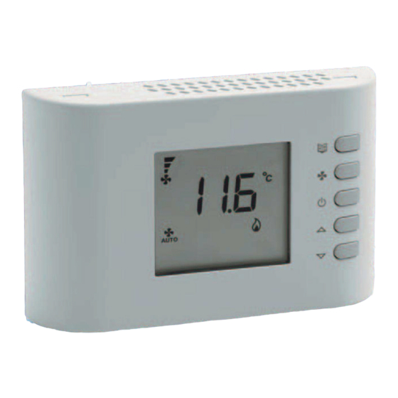
Page 13: Descrizione Dei Comandi
GENERALITÀ Questo dispositivo è un termostato digitale per il controllo della temperatura in ambienti riscaldati o raffrescati da fan-coil (ventilconvettori). Esso controlla in maniera proporzionale continua l’apertura delle valvole e la velocità del ventilatore su uscite 0..10V in modo da regolare la temperatura dell’ambiente nella maniera più... - Page 14 Se si preme ripetutamente il pulsante la visualizzazione cicla tra le diverse temperature. Dopo alcuni secondi di inattività la visualizzazione ritorna Impostazione velocità automatica del ventilatore. sulla temperatura ambiente. - Pulsante “ “ e “ “ Questi pulsanti permettono di impostare la temperatura ambiente se vengono premuti i pulsanti “...
- Page 15 trattini tanto più alta è la velocità del ventilatore. L’accensione dei simboli “ “ e “ diverso a seconda del tipo di impianto. raffrescamento). Sistema a due tubi: : riscaldamento, valvola aperta : raffrescamento, valvola aperta Sistema a quattro tubi: : valvola caldo aperta Allarme condensa: la regolazione è...
-
Page 16: Installazione
INSTALLAZIONE ATTENZIONE Per installare il dispositivo eseguire le seguenti operazioni seguendo le - La sonda di mandata deve essere installata in modo tale da immagini riportate da pagina 3 a pagina 7: rivelare correttamente la temperatura dell’acqua anche nel caso Sganciare la piastra attaccata alla base del termostato spingendola verso sinistra e facendo cosi’... -
Page 17: Collegamenti Elettrici
- Ruotare la calotta e spingere verso l’interno, con un dito, la linguetta “termostato di minima”; oppure può essere collegato un termostato plastica posta sulla parte inferiore della base (indicata dalla freccia bimetallico con funzione di “termostato di minima”. Agendo sulla in Fig. -
Page 18: Caratteristiche Tecniche
alimentati a 24V, seguire invece Fig. 8 nel caso siano alimentati a 230V. Campo visualizzazione: 0°C .. 99°C Isteresi: 2°C quanto la massa del segnale di ingresso è internamente collegata a uno Uscite proporzionali Range segnale: 0..10 V Precisione segnale: ±... - Page 19 APPENDICE INGRESSI ESTERNI - MORSETTI 3, 4 E 16 Il termostato dispone di tre ingressi esterni a cui è possibile associare SELEZIONE RISCALDAMENTO/RAFFRESCAMENTO funzioni diverse tramite i parametri C17, C18 e C19. La selezione del modo raffrescamento (estate) o riscaldamento (inverno), I segnali ai morsetti 3 e 4 possono essere collegati ai morsetti 3 e 4 di avviene tenendo premuto per alcuni secondi il pulsante menù...
- Page 20 USCITA 8 “ “ Il termostato può pilotare l’uscita 8 per realizzare una funzione speciale; si C23 e nella tabella 6 vengono illustrate le funzioni “ “ che è possibile realizzare. sul display e la regolazione della temperatura ambiente sarà sospesa. L’uscita 8 non è...
- Page 21 display visualizza la scritta “Or” (out of range). Se la sonda è interrotta molto bassa. oppure in corto circuito, il display mostra la scritta “EEE” (errore): la Nel caso invece si voglia usare un termostato bimetallico per questa regolazione del termostato non è più effettuabile e tutte le uscite restano funzione, è...
- Page 22 In questo tipo di impianto è possibile avere una regolazione con zona neutra Nel caso in cui, in questo tipo di impianto si usi anche la funzione impostando selezione raffrescamento/riscaldamento automatica (P02=1). “termostato di minima” in riscaldamento, il ventilatore non sarà mai Nel caso in cui, in questo tipo di impianto si usi anche la funzione “termostato di minima”, il ventilatore non sarà...
-
Page 23: Regolazione Della Temperatura
La funzione si attiva impostando un tempo sul parametro P25, il termostato integrale blanda. Un’azione integrale blanda o assente può far sì che non si conta il tempo di funzionamento del ventilatore e quando raggiunge la riesca a raggiungere nell’ambiente la temperatura impostata sul setpoint. soglia impostata in P25 “... - Page 24 CONFIGURAZIONE INSTALLATORE DESCRIZIONE PARAMETRI DI CONFIGURAZIONE PRINCIPALI termostato per adattarlo ai diversi tipi di ambienti e ai diversi tipi di tabella 1 e di seguito spiegati. P01: Selezione del tipo di impianto. premuti i pulsanti “ “ e “ Sistema a 2 tubi appare la scritta “COn pilota solamente una valvola sull’uscita della valvola caldo, sia in modo Da questo momento, premendo il pulsante “...
- Page 25 riscaldamento. P03 e P04: A seconda se si è in riscaldamento o raffrescamento viene usato Automatica: Il termostato decide automaticamente se passare al modo rispettivamente P03 o P04 raffrescamento o riscaldamento. deve regolare la temperatura agendo sulle valvole oppure sul ventilatore oppure su entrambi.
- Page 26 mentre da 0V per aprirla. della temperatura ambiente è quella interna al termostato oppure quella esterna (opzionale). P08: Con questo parametro si indica al termostato quale sonda intendiamo collegare sull’ingresso mandata (morsetti 13 e 14). P12: Questo parametro permette di correggere l’acquisizione della Con i valori 0 e 1 indichiamo che deve acquisire la temperatura da una temperatura ambiente.
- Page 27 una temperatura ambiente minima che viene mantenuta anche quando il P24: termostato è spento (da pulsante on/off). La regolazione a questa temperatura avverrà solo se il termostato è “termostato di minima” in modo raffrescamento. Nel caso la funzione non sia desiderata impostare questo parametro a 99. impostato in riscaldamento e la velocità...
- Page 28 DESCRIZIONE PARAMETRI DI CONFIGURAZIONE ESTESI C10: impostare con il pulsante “ventola“. tabella 2 e di seguito spiegati. In alcune installazioni può essere importante limitare la funzione del pulsante “ “. C01 e C02: La tabella 3 illustra le varie combinazioni che si possono scegliere. changeover automatico: nel caso non si usi tale funzione queste due informazioni non sono utilizzate.
- Page 29 Corretta rilevazione della temperatura ambiente pulsante “ “. Per ottenere una corretta acquisizione della temperatura ambiente è La tabella 5 illustra le varie combinazioni che si possono scegliere. necessario tenere presenti le seguenti indicazioni. C21: - Per una corretta regolazione della temperatura ambiente si consiglia di integrazione nell’impianto resistenza di integrazione.
- Page 30 Tabella 1: Tipo di Sistema a Sistema a Resistenza Resistenza impianto 2 tubi 4 tubi integrante Selezione estate/ Manuale Automatica Centralizzata inverno Solo Solo Valvole e Regolazione caldo valvole ventilatore ventilatore Regolazione Solo Solo Valvole e freddo valvole ventilatore ventilatore Tipo uscita Proporzionale Proporzionale...
- Page 31 Ritardo spegnimento Interna ventilatore (secondi) Sonda ambiente Soglia temperatura di Esterna mandata inverno (°C) Correzione temperatura Soglia temperatura di ambiente(°C) mandata estate (°C) Temp. Setpoint limite inferiore inverno (°C) (x 100 ore) Temp. Setpoint limite superiore inverno (°C) Temp. Setpoint limite inferiore estate (°C) Temp.
- Page 32 Tabella 2: Potenza media ventilatore Potenza massima ventilatore (%) Potenza minima ventilatore Soglia inferiore changeover resistenza attiva (°C) Limite inferiore segnale Soglia superiore ventilatore changeover (°C) Limite superiore segnale Banda proporzionale caldo ventilatore (°C) Funzione associata Tab. 4 Banda proporzionale freddo all’ingresso morsetto 3 (°C) Funzione associata...
- Page 33 Tabella 3: Parametro C10 - Selezione velocità ventilatore impostabili Tabella 4: PARAMETRI C17, C18, C19 - Funzione associabile agli da pulsante “ “. ingressi 3, 4 e 16. VALORE DESCRIZIONE VALORE DESCRIZIONE AUTO Nessuna funzione associata. AUTO Funzione “Estate/Inverno centralizzata“ (contatto chiuso= estate);...
- Page 34 Tabella 5: Parametro C20 - Selezione modi impostabili da pulsante Funzione “Stop regolazione“ invertito (contatto aperto=stop “ “. regolazione). VALORE DESCRIZIONE Funzione “Stop regolazione“ invertito (contatto aperto=stop regolazione) - il display visualizza l’icona “ “ (presenza) o “ “ (assenza) . Funzione “Stop regolazione“...
-
Page 35: Description Of Controls
INTRODUCTION This device is a digital thermostat for the temperature control in rooms the automatic fan speed. heated or cooled by fan coils. It provides a continuous proportional control More precisely 1 means the lowest speed, 2 the medium speed and 3 the over the valves and speed of the fan on the 0..10V outputs in order to fastest. -
Page 36: Display View
“ or “ “ are pressed during normal operation, the set-point temperature is displayed, along with the new set value. Even in this case, after a few seconds of inactivity the display readout Function is not available. returns to the room temperature. DISPLAY VIEW Delivery water temperature displayed. - Page 37 Four pipes system: : heating valve open Condensate alarm: regulation is suspended. : cooling valve open Electric heater system: : heating mode, electric heater on Motor alarm. : cooling mode, cooling valve open Integrating electric heater Valve error. system: : heating mode, valve open : cooling mode, valve open Occupied room: regulation reactivated or exit from “Economy“...
-
Page 38: Installation
INSTALLATION WARNING Carry out the operations below to install the device, while following the - The delivery water sensor must be installed in a way that it can images in page 3 to page 7: Release the plate attached to the thermostat base by pushing it to the stopped by the valve itself. - Page 39 WIRINGS outputs for a three speeds motor. If the proportional output is used, the This controller can be powered either with 230V~ or with 24V~. 0-10V signal will be available on terminal 11, while the reference ground on terminal 12. Connect the EC motor as shown in Fig. 12a. If the three The thermostat is factory set at 230V~, with jumper in position JP1, relay outputs for a three speeds motor are used, the outputs are available with frequency at 50Hz, with jumper in position JP4.
-
Page 40: Technical Features
terminal N. Signal precision: ±0.26V Minimum actuator impedance: When using ON/OFF valves, the heating output is available on terminal 6 1 0..10V output: 1430 Ohm and the cooling output on terminal 7 Fig. 12c. 2 0..10V outputs: 2860 Ohm In the case of two-pipes systems, only one valve needs to be connected to 3 0..10V outputs: 4290 Ohm the heating output. -
Page 41: Heating/Cooling Selection
APPENDIX The signal on terminal 16 cannot be connected to other thermostats. Functions that can be associated to the inputs are: HEATING/COOLING SELECTION “Centralised Heating/Cooling“ function: Heating or cooling modes are selected by keeping the “menu“ button When installations have multiple thermostats in a single building, the depressed for some seconds, until the display shows one of the following centralised inputs of each thermostat can be connected together and texts which indicates the current mode:... -
Page 42: Temperature Acquisition
CONTROL OF 0..10V PROPORTIONAL OUTPUTS level, so it is always possible to change the on/off status with the “ “ It is possible to connect several actuators to the same 0..10V output, button (if enabled). however it is necessary to make sure the output is not overloaded. Ensure “Motor alarm“... - Page 43 open or a short circuit, the display shows “EEE“ (error): in this situation, water for cooling the room. Follow the wiring diagram in Fig. 12e and functions which need the temperature are not performed. Fig. 12f. In this type of system it is suggested to set a delay on the fan switch-off on P22, so that when the electric heater is switched off, the CUT-OFF TEMPERATURE FUNCTION fan keeps running to cool the heater down.
-
Page 44: Economy Function
on P22, so that when the electric heater is switched off, the fan keeps running to cool the heater down. and cleaning or replacement. This regulator can warn the user when the When the fan motor is proportional driven, for the same purpose of cooling the heater down, it is possible to set on parameter C14 a minimum speed has been enabled. -
Page 45: Installer Configuration
temperature in the room. When the integral time is set to zero, no integral INSTALLER CONFIGURATION action is made and therefore the regulation is purely proportional (P type). When an integral time different from zero is set the resulting regulation is adapt it to the different types of plants and systems. - Page 46 DESCRIPTION OF MAIN CONFIGURATION PARAMETERS cooling mode or vice-versa. This automatic operation is different according to the system type as set with parameter P01. explained below. In case of a 4-pipes system or an “electric heater” system, the thermostat P01: System type selection. operates with a neutral zone.
- Page 47 turned on even after temperature has reached the setpoint; when fan only sensor is still used for the regulation purpose, even if its value can not is chosen the valve will be powered even after temperature has reached be displayed. the setpoint.
- Page 48 temperature when in heating mode. In details P13 is the lower limit, it valve opening to the fan turn-on, in order to allow some time for the heat P14 is the upper exchanger to heat-up or cool-down. P13 value P22: This parameter allows to set a delay time (in seconds) from the until 35.0°C.
- Page 49 DESCRIPTION OF EXTENDED CONFIGURATION PARAMETERS C11, C12 and C13: When the fan is controlled via the proportional output, 1, 2 and 3. explained below. These parameters are not used if the fan is controlled by the relays. C01 and C02: changeover function: if the function is not used this information is not C14: When the fan is controlled via the proportional output, this parameter applied.
- Page 50 C22: If the buttons are inactive for a few seconds the thermostat returns ROOM TEMPERATURE CORRECT ACQUISITION to display the room temperature. For a correct temperature acquisition it is mandatory to remember and When this parameter is set to 1, the thermostat displays the set-point apply the following tips: - In order to have an accurate room temperature acquisition the controller temperature instead of room temperature.
- Page 51 Integrating System type 2-pipes system 4-pipes system Electric heater electric heater Heating/cooling Manual Automatic Remote selection Heating Valves only Fan only Valves and fan regulation Cooling Valves only Fan only Valves and fan regulation Proportional, Proportional, Fan output type 3 speeds relays direct action inverse action Heating output...
- Page 52 Fan delay at Internal turn-off (seconds) Room temperature sensor Heating delivery External temperature threshold (°C) Room temperature Cooling delivery offset (°C) temperature threshold (°C) Heating set-point lower limit (°C) time (x 100 hours) Heating set-point upper limit (°C) Cooling set-point lower limit (°C) Cooling set-point upper limit (°C)
- Page 53 Medium fan power (%) Maximum fan power (%) Minimum fan power with Changeover electric heater ON lower threshold (°C) Fan signal lower limit Changeover upper threshold (°C) Fan signal upper limit Heating proportional band (°C) Tab. 4 Terminal 3 input function Cooling proportional band (°C) Tab.
- Page 54 Table 3: C10 parameter - Fan speed “ “ button limitation. Table 4: PARAMETERS C17, C18, C19 - Function associated to 3, 4 and 16 inputs. VALUE DESCRIPTION VALUE DESCRIPTION AUTO No function associated. AUTO “Centralised Summer/Winter“ function (closed contact = AUTO summer);...
- Page 55 Table 5: C20 parameter - On/Off “ “ button limitation . Reversed “Stop adjustment“ function (open contact = stop adjustment). VALUE DESCRIPTION Reversed “Stop adjustment“ function (closed contact = stop adjustment) - display shows the “ “ (present) or “ “...
Need help?
Do you have a question about the CR26 and is the answer not in the manual?
Questions and answers