
Summary of Contents for SSV MLS/160A
- Page 1 MLS/160A Soft Sensor System Reference SSV Software Systems GmbH Dünenweg 5 D-30419 Hannover Phone: +49 (0)511/40 000-0 Fax: +49 (0)511/40 000-40 Document Revision: 1.1 E-mail: sales@ssv-embedded.de Date: 2020-11-18...
-
Page 2: Table Of Contents
MLS/160A – System Reference CONTENT INTRODUCTION ....................... 3 Safety Guidelines ........................3 Conventions .......................... 3 Block Diagram ........................4 Nameplate ..........................4 Features and Technical Data ....................5 OVERVIEW ........................6 INTERFACES ........................7 JTAG/Debug – J1........................7 Primary RS485 Screw Terminal – J2 ..................8 Power Connector –... -
Page 3: Introduction
MLS/160A – System Reference INTRODUCTION This document describes the basic hardware and software components of the soft sensor MLS/160A. Safety Guidelines Please read the following safety guidelines carefully! In case of property or personal damage by not paying attention to this document and/or by incorrect handling, we do not assume liability. -
Page 4: Block Diagram
MLS/160A – System Reference Block Diagram Figure 1: Block diagram MLS/160A Nameplate Figure 2: Nameplate MLS/160A D o c u m e n t R e v i s i o n 1 . 1... -
Page 5: Features And Technical Data
MLS/160A – System Reference Features and Technical Data Processor Manufacturer/Type STM32 micro controller with ARM 32-bit Cortex-M3 Core Clock speed max. 72 MHz Memory 20 KB SRAM Flash 64 KB Interfaces Serial I/Os 1x RS485 half duplex, 115200 bps JTAG/Debug... -
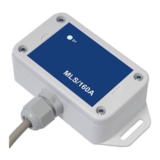
Page 6: Overview
MLS/160A – System Reference OVERVIEW Figure 3: Overview MLS/160A D o c u m e n t R e v i s i o n 1 . 1... -
Page 7: Interfaces
MLS/160A – System Reference INTERFACES JTAG/Debug – J1 Name Function VCC3 3.3 VDC Ground NTRST# Test Reset BOOT0 Boot0 Pin (please refer to STM32 datasheet) Test Data In TXD1 Debug Port TXD1 Pin Test Mode Select RXD1 Debug Port RXD1 Pin... -
Page 8: Primary Rs485 Screw Terminal - J2
Table 5: Pinout power connector CAUTION! Providing the MLS/160A with a higher voltage than the regular 12 .. 24 VDC ±10% could cause damaged device components! Do NOT turn on the power supply while connecting any cables, especially the power ca- bles. -
Page 9: Operating System
The microkernel itself comprises thread management, a priority-based scheduler, a power- ful API for inter-process communication (IPC), a system timer, and mutexes. All this makes it an ideal OS for the MLS/160A and opens up versatile options for own de- velopments, as well as benefiting from community driven enhancements. -
Page 10: A/B Boot Concept
MLS/160A – System Reference A/B Boot Concept The MLS/160A has an A/B boot concept is based on the RIOTBOOT bootloader. It enables, for instance, the Secure Device Update (SDU) function (please see chapter 4.2). The Flash memory of the STM32 MCU is divided in two so-called boot slots ("A" and "B") like shown in figure 4. -
Page 11: Secure Device Update (Sdu)
If the HMAC is invalid, the magic number is not changed and the slot remains inva- lid. Resetting the MLS/160A and checking if the slots are valid. If both slots are valid, • the slot with the higher version number is used, which should be the updated one. -
Page 12: Protocol Specification
IDLE state. UPDATE If the MLS/160A is in the IDLE state and receives the start update datagram from the re- mote station, it switches to the UPDATE state and the update process begins. After the up- date the MLS/160A returns to the IDLE state. Please refer to chapter 5.3 for a detailed de- scription of the update process. -
Page 13: Datagrams
MLS/160A – System Reference Datagrams Configuration This datagram has a fixed length of 5 bytes and is transferred at the beginning of the meas- uring from the remote station to the MLS/160A. 0x41: A TEMP GYRZ GYRY GYRX ACCZ ACCY... - Page 14 MLS/160A – System Reference Measuring This datagram is sent from the MLS/160A to the remote station after each measurement. It has a variable length depending on the configuration. If the respective measurement value is configured to be polled, the value will be transferred, otherwise the field is left out.
- Page 15 Update During the update process several datagrams are sent between the remote station and the MLS/160A. Figure 7 shows the update process in a diagram. Figure 7: Diagram of the update process D o c u m e n t R e v i s i o n 1 . 1...
- Page 16 Length in Bytes 0x55: U Table 11: Start update datagram from the remote station requestChunk() The MLS/160A switches from the IDLE in the UPDATE state and answers with a request datagram of 9 bytes length. Length in Bytes OFFSET MAXCL Table 12: Request datagram from the MLS/160A R: The ASCII character R (0x52) is the identifier of the request datagram.
- Page 17 This loop runs until ACTCL is smaller than MAXCL which means that the firmware binary file was transferred completely. requestHMAC() In this case the MLS/160A sends a verification datagram of 1 byte length with the ASCII character V (0x56) to the remote station. Length in Bytes...
- Page 18 If the HMAC is valid, the magic number of the updated slot is set back to "RIOT" and the slot is valid again and ready to boot. The MLS/160A sends an okay datagram of 1 byte length with the ASCII character Y (0x59) to the remote station.
-
Page 19: Mechanical Dimensions
MLS/160A – System Reference MECHANICAL DIMENSIONS All length dimensions have a tolerance of 0.5 mm. Figure 8: Mechanical dimensions of MLS/160A D o c u m e n t R e v i s i o n 1 . 1... -
Page 20: Connecting To An Rmg/941
MLS/160A – System Reference CONNECTING TO AN RMG/941 Connect the MLS/160A to an RMG/941 gateway like shown in figure 9. Figure 9: Wiring diagram for the connection of the MLS/160A to an RMG/941 Wire color Pin MLS/160A Pin RMG/941 White... -
Page 21: Helpful Literature
Information in this document is provided ‘as is’ without warranty of any kind. Some names within this document can be trademarks of their respective holders. © 2020 SSV SOFTWARE SYSTEMS GmbH. All rights reserved. D o c u m e n t R e v i s i o n 1 . 1...
Need help?
Do you have a question about the MLS/160A and is the answer not in the manual?
Questions and answers