Advertisement
Quick Links
Advertisement

Related Manuals for Applied Research and Technology Project Series

Summary of Contents for Applied Research and Technology Project Series
- Page 2 IMPORTANT SAFETY INSTRUCTION – READ FIRST This symbol, whenever it appears alerts you to the presence of uninsulated dangerous voltage inside the enclosure-voltage that may be sufficient to constitute a risk of shock. This symbol, whenever it appears, alerts you to important operating and maintenance instructions in the accompanying literature.
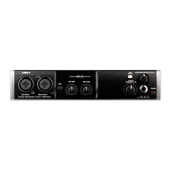
- Page 3 INTRODUCTION The USB PRE II is a high quality, 2-IN / 4-OUT digital recording interface intended for home studio and mobile recording applica- tions. It provides a pair of inputs that accept mic, instrument and line level signals. Equipped with high quality digital converters, the USB PRE II of- fers up to 32-bit /192kHz performance.
- Page 4 Key Features Include • High-Quality 32-bit A to D and D to A Converters • Sample rates from 44.1k to 192kHz • Low latency ASIO and WDM driver • Low noise mic preamps • High Z instrument inputs • Zero latency monitoring •...
- Page 5 DRIVERS ART provides a low latency ASIO driver, which you need to download from our website to use the unit with Windows. En- sure your DAW application, such as Cubase LE, supports ASIO I/O to take advantage of this driver and its control panel. The ASIO driver enables sample rates up to 192kHz with up to 6 streams of audio (2 in and 4 out).
- Page 6 CONNECTIONS Left and Right “Combo” jacks on the front allow for either XLR or 1/4-inch TRS input connections. The 1/4-inch Input connections are used for instrument or line level balanced or unbalanced signals. The high fixed input im- pedance works well with guitar and other passive instrument pickups.
- Page 7 OUTPUT LEVEL: Potentiometer controls the gain for chan- nel 1/2. Input Monitor: When the switch is engaged, a user can monitor the input signal from the 1/4-inch headphone jack. Headphone LEVEL (OUT CH3/4): Allows the user to ad- just the gain to the Headphone out jack. Headphone Jack: Access point for monitoring.
-
Page 8: Quick Start
QUICK START Connect the USB PRE II to your computer or mobile device through the USB cable provided. Connect your output jacks. Studio monitors are typically connected via a pair of ¼-inch cables to the Main Outputs. A pair of headphones can be connected to via the front panel. -
Page 9: Controls And Operation
CONTROLS and OPERATION Inputs Use the Left and Right input jacks to connect your microphone, instrument or line-level sources. Balanced and unbalanced ca- bles are both supported. The Left and Right Gain controls directly adjust the input ampli- fiers, giving you up to 50dB of clean gain. Set the controls coun- terclockwise to minimum gain when connecting the inputs. - Page 10 gain prior to connecting your microphone and applying phantom power. The Level Indicators around the channel gain pots respond to incoming signals and the level applied. Adjust levels to get a con- sistently green ring with occasional flashes of red. The red ring indicates 2dB below digital clipping and should light on musical peaks only.
- Page 11 Headphone Setup The USB Pre II routes the Headphone (OUT3/4) signal on an independent stereo path from the Main Outputs (OUT1/2). This gives the user the flexibility of creating unique Main and Head- phone monitor mixes in their DAW of choice. For listening to system sounds, user must select between the Main Outputs and Headphone output as follows.
- Page 12 macOS 11.x (Big Sur) and earlier Open Audio MIDI Setup USB II Audio Interface > Output Configure Speakers Choose between Front Left,Front Right (OUT 1/2) or 3,4 (OUT 3/4) Click Done...
- Page 13 Creating a Headphone Out Bus in Cubase Ensure you are using the USB II or USB IV ASIO driver Go to Studio > Studio Setup Set the ASIO Driver to USB II or USB IV de- pending on your product Create a headphone bus Go to Studio >...
- Page 14 ASIO Driver Configuration in Cubase (Windows) In order to take advantage of the low-latency ASIO driver pro- vided with the USB Pre IV, make the following adjustments in Cubase. Go to Studio > Studio Setup Click Audio System Select the USB II or USB IV from the ASIO Driver pulldown on the right Click Switch from the popup Click USB II or USB IV on the left panel...
-
Page 15: Input And Output
MIDI Input and Output Use the MIDI INPUT and MIDI OUTPUT jacks to pass MIDI data back and forth between your computer and devices such as MIDI keyboard controllers, drum machines and sequencers. The MIDI IN and MIDI OUT will show up as USB PRE II under your MIDI I/O selections. - Page 16 Setup The USB PRE II and USB PRE IV implement a USB-MIDI inter- face to connect your instruments, sequencers and other MIDI equipment to your computer. Here is how the USB PRE II’s MIDI presents itself in the Win- dows 10 Device Manager: Fig.
- Page 17 When your Windows application wants to use the MIDI inter- face, look for USB PRE II or USB PRE IV. This is how the USB PRE II MIDI I/O shows up on a MAC using Audio/MIDI setup MIDI Window. As you can see there is one in- put and one output that are not yet assigned.
- Page 18 Using the MIDI I/O in Cubase When you want to use the MIDI interface in Cubase, select the Studio Setup function and then select the MIDI Port Setup. Se- lect USB PRE II as seen in Fig. 3. Fig. 3 – Cubase MIDI Port setup...
- Page 19 Using the MIDI Device Manager, you can use the MIDI output after installing a device and setting the output to USB PRE II. Once a MIDI output is assigned, it will show up as an output se- lection on a MIDI track and Active in the MIDI Port Setup window. Fig.
-
Page 20: Warranty Information
Applied Research and Technology will provide warranty and ser- vice for this unit in accordance with the following warrants: Applied Research and Technology, (A R T) warrants to the orig- inal purchaser that this product and the components thereof will be free from defects in workmanship and materials for a period of three years from the date of purchase. - Page 21 This warranty gives you specific rights and you may have other rights, which vary from state to state. For units purchased outside the United States, an authorized distributor of Applied Research and Technology will provide ser- vice Fill in the following information for your reference:...
- Page 22 SERVICE The following information is provided in the unlikely event that your unit requires service. Be sure that the unit is the cause of the problem. Check to make sure the unit has power, all cables are connected cor- rectly, and the cables themselves are in working condition. You may want to consult with your dealer for assistance in troubleshooting or testing your particular configuration.
-
Page 23: Specifications
SPECIFICATIONS Input Connections: 2 - XLR/1/4-inch combo jacks, USB 1.0/2.0, MIDI DIN 5 Output Connections: Impedance Balanced 1/4-inch, 1/4-inch Headphone output, MIDI output Max input level: +15dBu Inst.,19dBu Bal. Line, +3.5dBu Input Impedance: >1M Ohms 1/4-inch input, >7k Ohms XLR input Max output level: +12dBu (CH1/2), +6.5dBu (CH3/4) Output Impedance:... - Page 24 All aluminum Note: 0 dBu = 0.775Vrms ART maintains a policy of constant product improvement. Therefore, specifications are subject to change without notice. Go to www.artproaudio.com for the latest information and sup- port on the USB PRE II Project Series.
Need help?
Do you have a question about the Project Series and is the answer not in the manual?
Questions and answers