Table of Contents
Advertisement
Quick Links
Advertisement
Table of Contents

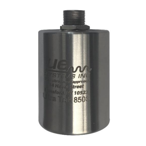
Summary of Contents for UE Systems UltraTrak 850S
- Page 1 UltraTrak 850S Smart Analog Sensor...
- Page 2 Information in this document is subject to change without notice and does not represent a commitment on the part of UE Systems. The information in this manual is not all-inclusive and cannot cover all unique situations.
-
Page 3: Table Of Contents
Table of Contents Safety Notes ........................4 Getting Started ......................5 1.1 Product Overview ....................5 1.2 Product Dimensions ....................5 1.3 Product Specifications .................... 6 1.4 Product Operation ....................6 1.4.1 Power Requirements ................... 6 1.4.2 Sensitivity Control ..................6 1.4.3 Wiring Connections .................. -
Page 4: Safety Notes
IMPORTANT SAFETY INFORMATION READ ALL INSTRUCTIONS BEFORE USE For your safety, the information in this manual must be followed to minimize the risk of fire, explosion, electric shock, and to prevent property damage, personal injury, or death. Improper use of your ultrasonic detector may result in death or serious injury. Observe all safety precautions. -
Page 5: Getting Started
Getting Started 1.1 Product Overview About The 850S The 850s is a modern ultrasound sensor and transmitter with state-of-the-art onboard data processing designed to detect early onset failures in industrial equipment. The 850s works in tandem with existing plant automation and measurement applications, providing the hardware required to detect changes in ultrasonic amplitude resulting from the degradation of equipment. -
Page 6: Product Specifications
1.3 Product Specifications Sensor Parameter Parameter Description Power Supply Voltage 23 VDC to 26 VDC Power Supply Current Draw 30mA DC Max, Typical Current Output Type Milliamp DC, Demodulated/Heterodyned Current Output Response Linear, Proportional to 0 dB to 100 dB of Change in Detected Ultrasonic Signal Current Output Range 0.500 mA DC to 16.280 mA DC @ 0.158 mA/dB of Change... -
Page 7: Wiring Connections
1.4.3 Wiring Connections Wire Colour Function Black Ground Power Supply (V _supply +24 VDC Nominal +23 to +26 Typical Current Output Clear 16.3 mA Max Green RF Shield 1.4.4 Current Output & Power Supply Current Draw The 850S’s quiescent power supply current draw is approximately 12mA. In sensing mode add the current output to the quiescent power supply current draw to obtain the operational power supply current draw (30mA maximum typical). -
Page 8: Common Applications
1.5 Common Applications Bearing Condition Monitoring & Lubrication 60%-80% of bearing failures are lubrication-related. Ultrasound provides a mechanism for detecting The 850s creates the ability to quickly Identify a early warnings of bearing or lubrication failure. The 850s’ patented Auto-Sensitivity Adjustment feature lack of lubrication and prevent over lubrication by providing real-time bearing friction data while enables users to automatically tune into bearing... -
Page 9: Valve And Steam Trap Monitoring
1.5 Common Applications Valve and Steam Trap Monitoring Inspect and Type of Emphasis on Safety Process Efficiency & Steam Trap & Valve Cost Reduction Maintain correct temperatures in your Inverted bucket, Avoid the dangers of process and preserve thermostatic, failing steam traps - the lifespan thermodynamic, float &... -
Page 10: Ultrasound Technology
2. Orifice Size The more the restriction of a fluid, less amplitude generated. A smaller diameter hole will not produce as much sound as a larger hole under similar flow conditions. 3. Pressure Differential Given identical leak sizes, when there is a greater pressure difference between the upstream and downstream sides, the leak with the greater difference will produce a louder signal. -
Page 11: Sensor Placement And Installation
Sensor Placement and Installation 2.1 Primary Considerations Bearing Proximity Place the sensor directly on the machine housing as close as possible to where the bearing is located for the most direct path of sound and vibration transmission. Placing the sensor as close as possible to the centerline of the bearing can also be considered to further optimize the signal coming directly from the bearings and avoid any potential distortion. -
Page 12: Additional Considerations
2.2 Additional Considerations Competing Sounds Whenever possible the sensor should be placed in locations that best isolate it from other sounds, both internal and external to the machine, that could hamper consistent monitoring of the bearing. A common example would be the increased electrical related sounds that can be heard the closer the sensor is placed to an electric motor’s wire termination junction box. -
Page 13: Mounting Options
Thread the sensor onto the stud. 2.4.2 Alternative: Fin Mount When a good spot to mount the sensor is not available, UE systems’ Motor Fin Mounts may be the perfect solution. selecting the proper Motor Fin Mount is accomplished by measuring the depth and width of the cooling fins where you want to locate the remote ultrasound sensor. -
Page 14: Accessories
2.5 Accessories Looking For More? UE Systems offers a variety of accessories to accommodate all your application needs! Thermo Isolation Yoke Mounting kit for thermal isolation. Used in application where mounting location is above the rated temperature of the sensor. The thermo... -
Page 15: Customer Support
Customer Support Have a question or need assistance with your sensor? Want more information regarding products or training? Contact Us UE Systems Inc. Toll Free – 800.223.1325 Phone – 914.592.1220 Fax – 914.347.2181 Email – info@uesystems.com OR Visit – www.uesystems.com...
Need help?
Do you have a question about the UltraTrak 850S and is the answer not in the manual?
Questions and answers