
Related Manuals for HOLT HI-35850


Summary of Contents for HOLT HI-35850
- Page 1 HI-35850 ARINC 429 Protocol IC 1x RECEIVER 1x TRANSMITTER ADK-35850 Application Development Kit Users Guide January 25, 2021 AN-35850 Rev. New Holt Integrated Circuits...
-
Page 2: Revision History
AN-35850 REVISION HISTORY Revision Date Description of Change AN-35850, Rev. New 01-25-2021 Initial Release Holt Integrated Circuits... - Page 3 HI-3585 but has a much higher 12MHz SPI frequency. The example board set includes an ARM Cortex M3 base board and the HI-35850 plug-in daughter card. The kit uses IAR as the development IDE and an integrated USB debugger port is included on the base board so no other USB programming adapters are needed.
-
Page 4: Evaluation Kit Contents
Upper HI-35850 daughter board and Lower MCU board with (Microchip/Atmel) ARM Cortex M3 16-/32-bit microprocessor, debug interface and regulated 3.3VDC power supply The HI-35850 daughter card is separable and useable for user prototyping on other platforms. Hardware Block Diagram Holt HI-35850 daughter card Main host ARM processor card +3.3V... -
Page 5: Push Buttons
Transmits maximum number of FIFO messages (32) continuously. Press ‘q’ to quit. WITCHES SWITCH DEFAULT DESCRIPTION SW 1 ON = SPI 12MHz Frequency for HI-35850. OFF = HI-3585 compatibility mode. Sets SPI frequency to 2.4MHz. SW 2 Available to user. SW 3 Available to user SW 4 Available to user. -
Page 6: Led Indicators
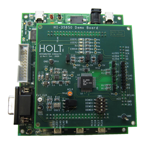
AN-35850 HI-35850 supply current measurements Jumper shunts J2, J1 and J3 can be removed to isolate 3.3V, +5 and -5V on the HI-35850 to allow current measurements of the HI-35850. External Host interface to the HI-35850 daughter board The HI-35850 daughter board can be separated from the MCU board and connected to a user FPGA or a host MCU for quick prototyping purposes. -
Page 7: Getting Started
Microchip/Atmel ARM Cortex M3 MCU. The next section instructs how to install the IAR EWARM IDE and the Holt demonstration program. The supplied demo program on the USB memory stick is the same demo already programmed in MCU flash memory. - Page 8 HyperTerminal is not included with these versions of Windows. Install the free open-source terminal emulation program, TeraTerm 4.71, by running the provided teraterm-4.71.exe installer program from the Holt CD. Accept the license agreement stating redistribution is permitted provided that copyright notice is retained. The notice can be displayed from the TeraTerm window by clicking Help then clicking About TeraTerm.
- Page 9 Press 'H' for this help menu, or press any valid menu key. >> It is highly recommended to first review the HI-35850 data sheet to gain a basic understanding of the device so you get the most benefit from the demos and utilities described in this guide.
- Page 10 Nearly all menu commands entered on the console instruct the ARM MCU to issue SPI Op Codes to write or read data in the HI-35850. The host configures the HI-35850 by writing to a Control Register using the SPI interface.
- Page 11 4C 4D 4E 4F 50 51 52 53 54 55 56 57 58 59 5A 5B 5C 5D 5E 5F 60 61 62 63 64 65 66 67 68 69 6A 6B 6C 6D 6E 6F 70 71 72 73 Holt Integrated Circuits...
- Page 12 Demo ‘c’: Cycle between the ACLK divisor selections listed in the data sheet. Once this has been invoked the Divisor is in use. The Holt daughter card has an on-board 1MHz oscillator so a divisor of 1 should be used. To use a 2, 4, 8 or 10MHz clock a jumper on the board can be used to select between the 1MHz oscillator and an external clock applied to TP13.
- Page 13 Demo for ARINC Label Recognition (filtering). The HI-35850 Receiver has the ability to filter out messages based on the Label value of the ARINC 429 message. Normally this feature is off and is enabled by first writing to a 256 bit label look up table using Opcode 0x06 then enabling the look up table by setting CR2 high in the Control Word.
- Page 14 1. Installed IAR Systems Embedded Workbench for ARM (EWARM ) compiler is required BEFORE adding the Holt demo project, so all Atmel board library files and the demo project folder are created in the proper locations. Follow the “Holt HI-35850Demo Project Installation Guide” found in the Project folder on the Holt CD-ROM.
- Page 15 3. Debug requires an interface between the computer running IAR Embedded Workbench® and the HI-35850 Application Development Kit. Connect the small end of the provided USB cable to the evaluation board USB connector marked DEBUG. Connect the other end of the USB cable to a free computer USB port.
- Page 16 AN-35850 5. If problems occur with IAR installation or with using the IAR debugger, two Holt technical notes are provided to help resolve these issues included on the Holt USB memory stick. 6. The demo project only uses unsigned integer variables. Optionally turn off the nuisance compiler message that occurs when a variable’s most significant bit toggles.
- Page 17 5. The Holt low level SPI drivers set nCS low during SPI access then high again at the end directly using a GPIO pin configuration. It must be controlled by software for compatibility with the way Holt SPI operates.
- Page 18 Project File List with Selected Descriptions HEADER FILES WITHOUT CORRESPONDING C FILES driver_3585_850.c/h Contains all macros for the HI-35850 including define statements for registers, control register bits, Op Codes and selected table Host Cortex M3 SPI low-level SPI drivers and start addresses.
- Page 19 48MHz clock source. The SPI block divides this by 4 for a 12MHz SPI clock rate which is the maximum for the HI-35850. There is no lower frequency limit but most application should use at least a 1MHz rate for reasonable performance.
- Page 20 Holt Integrated Circuits, Inc. Bill of Materials PCB P/N: HV057 HI-35850 44-QFP Evaluation Board Rev. A Item Qty Description Reference Digikey P/N Mfg P/N PCB, Bare, Evaluation Board NewTeck PCB# 18777 Capacitor, Cer 0.1uF 20% 50V Z5U 0805 C1,C8,C10,C11,C13 399-9157-1-ND...
- Page 21 PA15 SCK nLED5 PA31 nLED1 LT3463A nLED2 VREF LT3463AEDD#PBF-ND SHDN2 Header 2x20 Header 2x20 100K Header 2x20 0805 DEMO 0 switch: HI-35850 Default = ON(closed) HI-3585 = OFF 402K 10pF 10uH 0805 1210 CON2 0805 B0540W CON2 SOD123 4.7uF 10uF 0.1uF CON2 0.1uF...
- Page 22 Bill of Materials ARM Cortex M3 MCU Board Revised: 9 Sept 2011 Item Description Reference DigiKey Mfr P/N PCB, Bare, Evaluation Board, -------- revision B or C Ferrite Bead, 220 Ohm @ 732-1602-1-ND Wurth 742792034 100MHz 300mA DC 0805 Capacitor, Ceramic 10nF 10% C1,C42 399-1158-1-ND Kemet C0805C103K5RACTU...
- Page 23 Test Point, Orange Insulator, 5008K-ND Keystone 5008 0.062" hole Test Point, Yellow Insulator, 5009K-ND Keystone 5009 0.062" hole Test Point, Hole / Pad Only TP5,TP6 IC, MCU 32-Bit 256KB Flash, ATSAM3U4EA-AU-ND Atmel ATSAM3U4EA-AU 144-LQFP IC, ESD Protection Array 3- 296-21885-1-ND Texas Inst TPD3E001DRLR Channel SOT-5 IC, RS232 Driver/Receiver...
- Page 24 LOWER CIRCUIT BOARD STACKING UPPER CIRCUIT BOARD J3,J4 & J5 ARE DUAL-ROW STACKING RECEPTACLES (LOWER BOARD) AND HEADERS (UPPER BOARD). HOLT INTEGRATED CIRCUITS, Mission Viejo, CA, USA Title Title Title ARM CORTEX M3 MICROCONTROLLER BOARD ARM CORTEX M3 MICROCONTROLLER BOARD...
- Page 25 PC14 PC30 PC14/NPCS2 PC30/DA6 PC15 PC31 PC15/NWR1/NBS1 PC31/DA7 ARM CORTEX M3 PIO HOLT INTEGRATED CIRCUITS, Mission Viejo, CA, USA Title Title Title ARM CORTEX M3 MICROCONTROLLER BOARD ARM CORTEX M3 MICROCONTROLLER BOARD ARM CORTEX M3 MICROCONTROLLER BOARD Size Size Size...
- Page 26 10uH/100mA PROVISIONAL 0805 MURATA LQM21FN100M70 ARM CORTEX M3 MCU 100nF 100nF 100nF 100nF HOLT INTEGRATED CIRCUITS, Mission Viejo, CA, USA 10uF 10uF Title Title Title ARM CORTEX M3 MICROCONTROLLER BOARD ARM CORTEX M3 MICROCONTROLLER BOARD ARM CORTEX M3 MICROCONTROLLER BOARD 4.7uF...
- Page 27 100K 100K 100K 100K PB17 nSW1 PB18 nSW2 BOARD I/O HEADERS, BUTTONS HOLT INTEGRATED CIRCUITS, Mission Viejo, CA, USA Title Title Title ARM CORTEX M3 MICROCONTROLLER BOARD ARM CORTEX M3 MICROCONTROLLER BOARD ARM CORTEX M3 MICROCONTROLLER BOARD Size Size Size...
- Page 28 RTS1 PA22 T2IN T2OUT CTS1 PA23 R2OUT R2IN USB & RS-232 SERIAL HOLT INTEGRATED CIRCUITS, Mission Viejo, CA, USA Title Title Title ARM CORTEX M3 MICROCONTROLLER BOARD ARM CORTEX M3 MICROCONTROLLER BOARD ARM CORTEX M3 MICROCONTROLLER BOARD Size Size Size...
- Page 29 100uF 100nF 100nF 150R 150R 100nF 100nF 22uF 22uF POWER SUPPLY HOLT INTEGRATED CIRCUITS, Mission Viejo, CA, USA Title Title Title ARM CORTEX M3 MICROCONTROLLER BOARD ARM CORTEX M3 MICROCONTROLLER BOARD ARM CORTEX M3 MICROCONTROLLER BOARD Size Size Size Document Number...
- Page 30 10nF 10nF RESET Header 2 x 10, Shrouded Header 2 x 10, Shrouded DEBUG INTERFACE HOLT INTEGRATED CIRCUITS, Mission Viejo, CA, USA Title Title Title ARM CORTEX M3 MICROCONTROLLER BOARD ARM CORTEX M3 MICROCONTROLLER BOARD ARM CORTEX M3 MICROCONTROLLER BOARD...
Need help?
Do you have a question about the HI-35850 and is the answer not in the manual?
Questions and answers