Table of Contents
Advertisement
Quick Links
Advertisement
Table of Contents

Subscribe to Our Youtube Channel
Summary of Contents for HW Group HWg-PWR 3
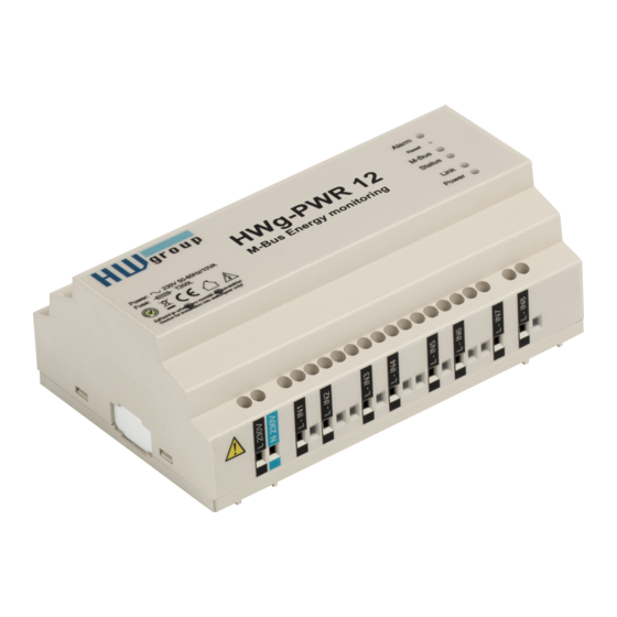
- Page 1 HWg-PWR 3/12/25 MANUAL...
-
Page 2: Package Contents
HWg-PWR 3 / 12 / 25 MANUAL HW group Package contents A complete shipment contains the following items: HWg-PWR25 (HWg-PWR12) unit Printed manual + datasheet Safety information The device complies with regulations and industrial standards in force in the Czech Republic and the European Union. -
Page 3: Table Of Contents
HW group Table of Contents Package contents ............................. 2 Safety information ............................2 What is HWg-PWR 3 / 12 / 25 .......................... 4 Usage examples ............................4 Basic features of HWg-PWR12/25 ........................5 Description of connectors and connections ....................6 LED indicators ............................. -
Page 4: What Is Hwg-Pwr 3 / 12 / 25
HWg-PWR 3 / 12 / 25 MANUAL HW group What is HWg-PWR 3 / 12 / 25 The HWg-PWR is an Ethernet-enabled device for remote monitoring and metering of electricity, heat, water or gas consumption using electricity, water, gas, heat, or other meters equipped with the M-Bus interface. -
Page 5: Basic Features Of Hwg-Pwr12/25
HWg-PWR 3 / 12 / 25 MANUAL HW group Basic features of HWg-PWR 3 / 12/ 25 Ethernet: RJ45 (100BASE-TX) WEB: Embedded WEB server / GUI M-Bus meters: up to 3 / 12 / 25 M-BUS meters (electricity, gas, ...) ... -
Page 6: Description Of Connectors And Connections
HWg-PWR 3 / 12 / 25 MANUAL HW group Description of connectors and connections LED indicators Power (green) – lights up when the device is powered. Alarm (red) – lights up whenever a monitored variable is in alarm. -
Page 7: Restoring Factory Defaults
HWg-PWR 3 / 12 / 25 MANUAL HW group Default switch: Restoring factory defaults Press and hold the Reset (Default switch), connect power, and hold the switch pressed for 10 more seconds. The HWg-PWR resets itself to factory defaults. Be careful when working with HWg-PWR in a distribution box. -
Page 8: Technical Specifications
HWg-PWR 3 / 12 / 25 MANUAL HW group Technical specifications Ethernet port + Interface RJ45 (10BASE-T / 100BASE-Tx) + Compatibility Ethernet: Version 2.0/IEEE 802.3 + Supported protocols IP: ARP, TCP/IP (HTTP, SMTP, Modbus/TCP), UDP/IP (SNMP, SNMP Traps, DHCP, SNTP) + SNMP Ver:1.00 compatible, partial ver. -
Page 9: First Steps
HWg-PWR 3 / 12 / 25 MANUAL HW group First steps 1) Connecting the cables HWg-PWR connects directly to a 110/230VAC supply; therefore, it should be installed by qualified personnel only! Connect the unit to the Ethernet (a patch cable to a switch, or a cross-over cable to a PC). -
Page 10: Www Interface Of The Device
HWg-PWR 3 / 12 / 25 MANUAL HW group Restoring factory defaults Right-click a device MAC address. Within 60 seconds after powering up the unit, factory defaults can be restored using UDP Config. Disconnect power, press the Default switch, power up the device and wait for 10 seconds. -
Page 11: Adding Connected Meters And Measured Values
HWg-PWR 3 / 12 / 25 MANUAL HW group Adding connected meters and measured values Start the WWW interface of HWg-PWR and go to the Device menu. The list of detected meters is empty. Individual meters are always added to HWg-PWR manually. A tool for automatic... -
Page 12: Automatic Discovery Of Meters
HWg-PWR 3 / 12 / 25 MANUAL HW group Automatic discovery of meters: 1. At the Device Base Parameters page, fill in the M-Bus Scan section: Serial Baudrate – Communication speed. The default is 2400 but this can differ for various meters – see the meter documentation. - Page 13 HWg-PWR 3 / 12 / 25 MANUAL HW group Note: If HWg-PWR does not find any connected meters, re-check the M-Bus connection (in particular its polarity) and the baudrate and parity configuration, or try to look up these values in the documentation of your meter. Repeat the search until you find all meters.
-
Page 14: Activating And Adding Discovered Meters To Hwg-Pwr
HWg-PWR 3 / 12 / 25 MANUAL HW group Activating and adding discovered meters to HWg-PWR 1. In the Device menu, select the desired meter. The Edit xMeter section displays. 2. Turn on the meter in the system (change Enable to Enable). - Page 15 HWg-PWR 3 / 12 / 25 MANUAL HW group 11. Click Save to save your changes. Important: In order to find meter variables, the meter must be enabled and saved. It is not possible to scan values without saving the meter configuration first! Repeat steps 1 to 3 to add all required meters.
-
Page 16: Www Interface
HWg-PWR 3 / 12 / 25 MANUAL HW group WWW interface Home tab The Home tab displays current readouts of all enabled values of a meter, together with status symbols. The value is within its allowed range (Saferange) The value is out of its allowed range (Saferange) M-Bus communication error –... -
Page 17: Graph Tab
HWg-PWR 3 / 12 / 25 MANUAL HW group Graph tab The Graph tab lets you plot a graph of the measured values. When this function is selected, all stored data from the device are read into the web browser. - Page 18 HWg-PWR 3 / 12 / 25 MANUAL HW group Graph Config tab Configures the logging parameters common for all measured values. Period – Period for storing to the memory. If the Period is shorter than the Meter M- Bus Read period, the most recently retrieved data are stored multiple times.
-
Page 19: General Setup Tab
HWg-PWR 3 / 12 / 25 MANUAL HW group General Setup tab The General Setup tab is used to configure basic operating parameters of HWg-PWR. Base section Device Name – Custom name for the HWg-PWR unit. Allows distinguishing individual units in a network. -
Page 20: Snmp Tab
HWg-PWR 3 / 12 / 25 MANUAL HW group SNMP tab The SNMP tab is used to configure SNMP communication parameters and target destinations for SNMP Trap alarms. General SNMP Settings section System Name – Name of HWg-PWR within SNMP. - Page 21 HWg-PWR 3 / 12 / 25 MANUAL HW group Show OID keys table This function prints the entire tree of variables with their full SNMP OID and type explanation. The MIB file for connecting the HWg-PWR to third-party monitoring systems is available under the Download MIB file link.
-
Page 22: Modbus Tcp Server
HWg-PWR 3 / 12 / 25 MANUAL HW group Modbus TCP Server HWg-PWR can supply data to SCADA systems using the ModBus/TCP protocol. ModbusTCP Enable – Enables the ModBus/TCP protocol. ModbusTCP Port – Port for the Modbus/TCP protocol (default is 502). -
Page 23: E-Mail Tab
HWg-PWR 3 / 12 / 25 MANUAL HW group E-mail tab The E-mail tab is used to define the e-mail server and the parameters for sending alarm e- mails (beginning or end of an alarm). HWg-PWR only supports unencrypted SMTP connections. - Page 24 HWg-PWR 3 / 12 / 25 MANUAL HW group Periodic Email Configures the period for sending non-alarm messages. Periodic Data mail – Periodically e-mails the log of measured values. The log only contains values which have logging enabled! o Datalog file type – Select datalogs type – CSV or BIN (Binary – see chapter Datalog format ) ...
-
Page 25: Time Tab
HWg-PWR 3 / 12 / 25 MANUAL HW group Time tab The Time tab is used to configure system time and automatic synchronization with a timeserver. SNTP Setup section SNTP Server – IP address or host name of the time synchronization server. Default is time.nist.gov. -
Page 26: Záložka Remote Sms
HWg-PWR 3 / 12 / 25 MANUAL HW group Remote SMS tab This tab is used to setup the alarm SMS parameters. The SMS messages are sent through a remote SMS gateway with the netGSM protocol support. Remote SMS setup section ... -
Page 27: Input Tab
HWg-PWR 3 / 12 / 25 MANUAL HW group Input tab This tab is used to configure the parameters of dry contact inputs. Input Dry Contacts section For each input, you can define: Name – Name of the input, shown at the homepage and in alarm messages. -
Page 28: Portal
HWg-PWR 3 / 12 / 25 MANUAL HW group Portal This tab is used to setup parameters to send the data to a remote portal using HWg-PUSH. You can find out more about the protocol and portal solution support here: http://www.hw-... -
Page 29: Device Tab
HWg-PWR 3 / 12 / 25 MANUAL HW group Device tab This tab is used to discover connected meters (Device), set their parameters, and to subsequently find and configure the values provided by individual meters. Device List section The Device List section lists all connected meters together with their type (Medium) and M-Bus address (Address). - Page 30 HWg-PWR 3 / 12 / 25 MANUAL HW group Edit xMeter section Enable – Enables or disables the meter within HWg-PWR. When a meter is disabled, values are not detected or read but the configured parameters remain stored. This can be used to temporarily turn off the reading and recording for a particular meter (during maintenance etc.)
- Page 31 HWg-PWR 3 / 12 / 25 MANUAL HW group Value Table section The Value Table section displays information about discovered values from a particular meter – their names (Name), units of measurement (Unit), current readings (Value), and whether logging is enabled. Each value is assigned a unique ID within HWG-PWR for use in XML and SNMP communication.
- Page 32 HWg-PWR 3 / 12 / 25 MANUAL HW group Edit y.Value on x.Meter tab State section State – Turns on/off the respective variable. Logging section Logging - Enables logging of values into the internal memory, at intervals specified at the Log tab.
- Page 33 HWg-PWR 3 / 12 / 25 MANUAL HW group Billing section Billing – Enables conversion of the measured value to currency (creating a virtual value tied to the actual value). Further on, this variable will be reported in terms of the measured quantity as well as its monetary equivalent.
-
Page 34: System Tab
HWg-PWR 3 / 12 / 25 MANUAL HW group System tab The System tab is used to access the most important system information, such as uptime or firmware version, and to perform operations such as HWg-PWR restart or firmware update. - Page 35 HWg-PWR 3 / 12 / 25 MANUAL HW group Connecting to the Portal 1) First connect the device to your network and set the network parameters (First Steps chapter in the user manual). 2) Then open the WWW setup on the Portal tab. In the Portal Config section, please tick the Portal option, save the changes with a Save button and then press the Manual Push button.
- Page 36 HWg-PWR 3 / 12 / 25 MANUAL HW group 3) By clicking a link SensDesk.com: register your IP sensor, you will be redirrected to a login page of SensDesk.com portal. 4) In case you already have a user account, please enter your login details and the device will be automatically assigned to your account.
- Page 37 HWg-PWR 3 / 12 / 25 MANUAL HW group 5) Enter the login details for your new account and a correct e-mail address. This e-mail address has to be unique for the server (cannot be already registered by another user).
- Page 38 HWg-PWR 3 / 12 / 25 MANUAL HW group 7) If you check your user account configuration (My Account link), you will find your Push Device Password. This password, together with your login name, identifies the device in communication with your account and in communication of mobile applications with SensDesk.
-
Page 39: Meter Types
HWg-PWR 3 / 12 / 25 MANUAL HW group Meter types With respect to the mode of operation, meters can be classified as: Mains-powered (electricity meters) Battery-powered (heat meters, water meters, gas meters etc.) Manufacturers of battery-powered meters may restrict the number of read operations within a certain time interval in order to maintain battery life. -
Page 40: Datalog Format Of Devices Hwg-Pwr And Hwg-Ares
HWg-PWR 3 / 12 / 25 MANUAL HW group Datalog format of devices HWg-PWR and HWg-Ares The data is stored in a simple binary format: <record1>< record2>< record3><record4><record5>…<recordN> The record format is following: Sensor ID (2 bytes) TimeStamp (4 bytes) - Page 41 HWg-PWR 3 / 12 / 25 MANUAL HW group /* Special pragma for Borland C++ Builder – other compilers probably use a different way * how to say to compiler an information about structures packing #pragma pack(push) #pragma pack(1) typedef struct { unsigned __int16 val_id;...
-
Page 42: Mechanical
HWg-PWR 3 / 12 / 25 MANUAL HW group Mechanical September 2013 page 42... - Page 43 HWg-PWR 3 / 12 / 25 MANUAL HW group September 2013 page 43...
-
Page 44: Accessories
HWg-PWR 3 / 12 / 25 MANUAL HW group Accessories DHZ 5/63-M-BUS Single-phase 63A electricity meter with M-Bus Three-phase, two-tariff, 63A electricity meter with M-Bus ED 310.DB HWG and S0 M-Count 2C Converter and datalogger, 2x pulse output (S0) / M-Bus DHZ 5/63-M-BUS ED 310.DB HWG...
Need help?
Do you have a question about the HWg-PWR 3 and is the answer not in the manual?
Questions and answers